Powers 595 Series 11 Self-Operating Temperature Regulators - Type WM 3-Way Water Mix User Manual
Page 6
6
4.
Figure 8. Remove housing bolts [6] and nuts [7] and tempera-
ture adjustment setting scale [8] and lift off thermal system [1]
(housing, bellows, capillary, and bulb).
5.
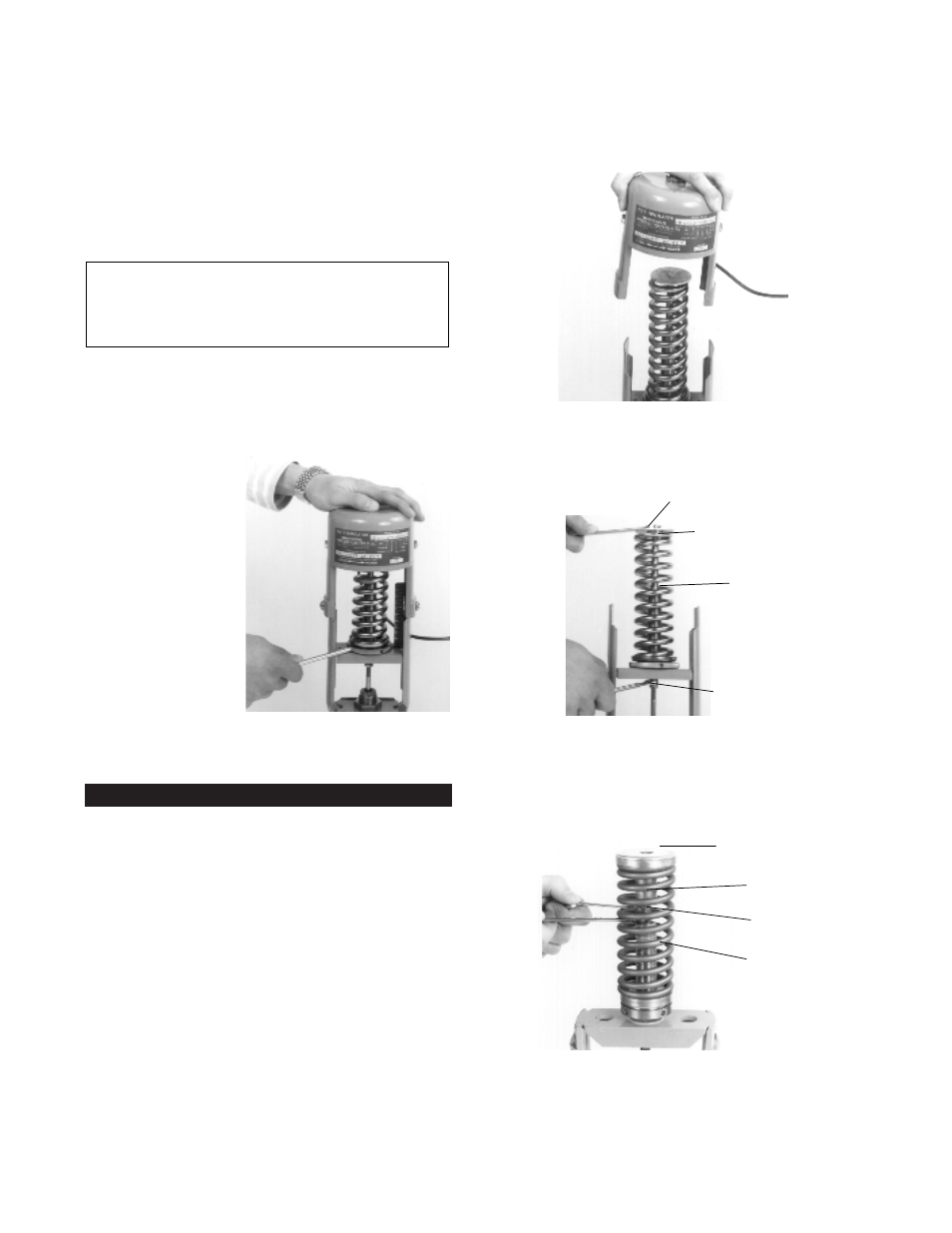
Figure 9A. For the 1/2" to 2" valves, use one 3/8" wrench and
one 5/16" wrench, carefully loosen and remove piston plate
assembly [2,3] from the stem extension [4].
Lift off spring [19].
Figure 9B. For the 2-1/2" to 4" valves, use two 3/8" wrench-
es to carefully loosen piston plate/shank [3] from the stem
extension [4]. Make sure the spring is fully decompressed,
slowly remove piston plate assembly. Lift off the spring seat
and the spring.
7.
Without a well: Remove bushing from the bulb and screw it
into the tank. Insert the thermostatic bulb through the bushing
and tighten the union nut.
With a well: Do not use bushing. Screw well into tank, insert
bulb directly into well, and tighten union nut.
ADJUST CAPILLARY TUBING
8.
Coil the extra capillary, and position away from regulator oper-
ation where it is subjected to room temperature only.
ADJUST SET POINT
All regulators are factory set to control near mid-range operating
temperature.
9.
When adjusting the set point, make certain all fluids are flow-
ing through the
valve and are at the
operating pressure
of the system.
10. Figure 7. Make all set
point temperature
changes by insert-
ing the temperature
adjustment rod into
one of the holes of
the adjusting nut
assembly. (Use the
temperature adjust-
ment setting scale
only for reference)
To Raise the set
point: Turn rod left
to right (counter-
clockwise from top).
To Lower the set
point: Turn rod right
to left (clockwise from top).
MAINTENANCE
Numbers in brackets [#] refer to part numbers on pp. 12 & 13.
To fully disassemble regulator from valve
1.
Figure 3. For 2-1/2” to 4” valves, replace bellows stops
before performing any service or maintenance.
2.
Before disassembly, the bulb must be cooled 30°F (16°C)
below the lowest point on the thermal system range, and flow
through the valve must be stopped.
3.
Figure 7. Relieve all pressure on the spring by turning adjust-
ing nut assembly [31] fully right to left (clockwise from top).
WARNING: DO NOT kink, cut, sever or file the tubing.
DO NOT disconnect tubing from bulb or bellows
assembly. This can render the thermal system inopera-
ble and result in severe process overheating.
7. ADJUSTING SET POINT
8. REMOVE HOUSING AND THERMAL SYSTEM
3/8" Nut
5/16" Nut
Piston Plate
Assembly
Spring
9A. (1/2" TO 2") REMOVE PISTON PLATE AND SPRING
9B. (2-1/2" TO 4") REMOVE PISTON PLATE/SHANK AND SPRING
Piston Plate/
Spring Seat
3/8" Shank
3/8" Stem
Extension
Spring