Powers 450 Infrared ESP HydroPanel II Infrared Sensor System User Manual
Technical instructions, Description, Installation
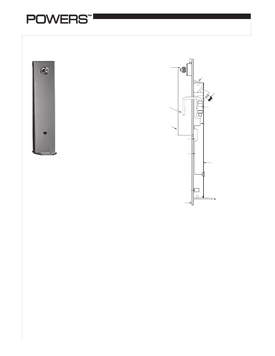
ESP TM Hydropanel TM II Sensor System
With Infrared Sensor Single Shower Application
IS-P-450S
Transformer
(Box Type
Shown)
Showerhead
(Fixed Shown)
Solenoid
Valve
(Non-metallic
Shown)
Control Box
Mounting
Bracket
Soapdish
Hydropanel
Shrouding
Finished
Wall
Wiring
Wiring
Wiring
Chrome-Plated
End Cap
Inlet Piping
(Supplied
by others;
thru-wall or
from ceiling)
Technical Instructions
The ESP (Electronic Sensor
Plumbing) Hydropanel II Infrared
Shower System combines modular
shrouding with the convenience
of electronic water control. The
Hydropanel II shrouding provides a
concealed shower system where
in-wall piping does not exist or
may not be practical. The ESP
Infrared Shower System relies on
infrared technology to sense the
presence of a user and deliver
tempered water to the shower
with completely hands free opera-
tion. The shower automatically
turns on when the bather enters
the infrared field of the sensor,
and continues to operate as long
as the bather stands in front of the
sensor, up to the field adjustable
run-time.
The Powers Series 450 ESP
Infrared shower systems come
complete with stainless steel
Hydropanel II shrouding, ESP
Infrared Shower System, showerhead, piping, with or with-
out soapdish and mounting hardware.
The ESP Infrared Sensor Assembly consists of infrared sen-
sor, modular junction box, wiring, solenoid valve and 24V AC
transformer.
The following instructions serve as a guide for installation
of the Powers ESP Hydropanel II Infrared Sensor shower
systems. Powers recommends good safety practices and
care when installing electrical equipment. Please follow the
procedures as outlined. For additional assistance, please
call the Powers Applications Engineering Department at
1-800 669-5430.
Description
n
Installation
n
Precautions Before Installation:
• Use a 24V AC step-down transformer for single and group
shower applications.
• Do not supply power to, or plug in, the transformer until all
other wiring is complete. To prevent permanent damage to
the transformer, do not allow power transformer wires to
touch during wiring.
• Before connecting the solenoid valve, flush Hydropanel
supply lines to ensure supply water will be free of grit,
sand, etc. The solenoid valve requires water free of all
foreign
matter to operate properly.
• To inhibit corrosion, a waterproof, multi-purpose, aerosol
grease may be sprayed onto all electrical contacts.
• Follow the national/local codes and regulations for all
electrical wiring and plumbing.
• Use stainless steel screws for all component installations.
Tools Required:
• Slotted and Phillips screwdrivers
• Drill with 5/8" bit
• Pipewrenches
• Pipe dope/sealing compound
• Allen Wrench(s) (included with shrouding)
The ESP Hydropanel II Shower System includes a solenoid
valve (brass) which receives tempered water though pre-
installed piping. A Powers master mixing valve such as the
MM430/SH1430 Thermostatic mixing valve, or Hi-Lo cabinet
supply fixture, can be used to supply safe comfortable water to
the ESP Hydropanel shower system.
Figure 1. ESP
Hydropanel II
Series
50-i000003WD
Infrared System
Figure 2.
Typical Shower Installation