Powers 450-410P HydroPanel II Shower System with HydroGuard PB410 Pressure Balancing Valve User Manual
Technical instructions, Description, Specifi cations
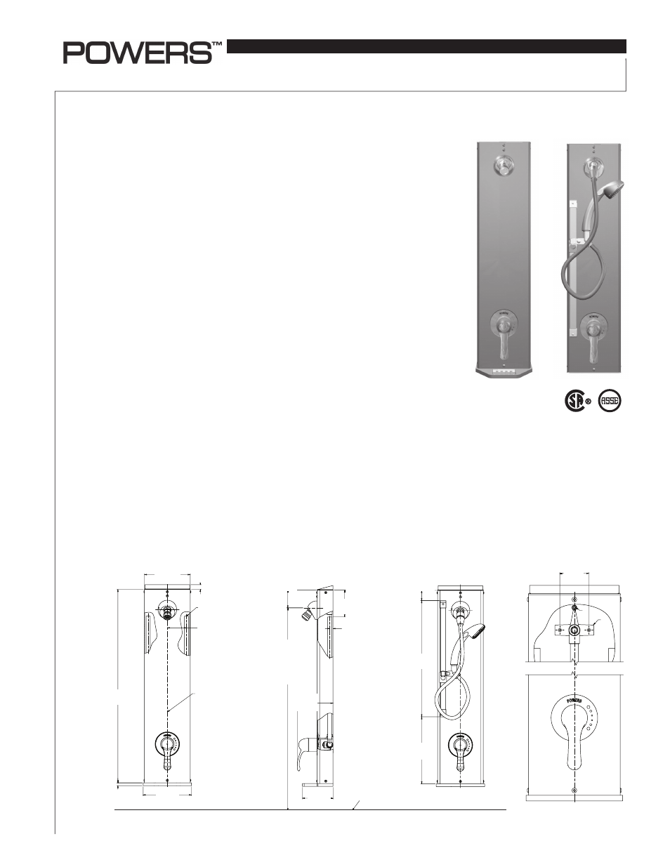
Description
■
HydroPanel II
™
Shower System
with HydroGuard
®
PB410 Pressure Balancing Valve
Technical Instructions
IS-P-450-PB410
Specifi cations
■
The Powers HydroPanel II
™
Shower System with HydroGuard
®
PB410 valve
combines pressure-balanced water control with the convenience of modular
shrouding. It provides a concealed shower system where in-wall piping
does not exist or may not be practical. The HydroGuard
®
PB410 features
heavy cast brass construction, a poppet-type equalizing valve as part of
a replaceable cartridge. The poppet-type construction offers a distinct
advantage in that it will not stick because of lime buildup or foreign particles
in the supplies. The metal-to-metal temperature limit stop prevent acciden-
tal scalding caused by over adjustment of handle. It also features integral
checkstops. HydroPanel II
™
comes complete with stainless steel shrouding,
PB410 valve, piping, end cap and mounting hardware. Some models feature
a stainless steel soap dish. Some models feature an ADA compliant lever
handle. An optional hand shower comes preassembled.
HydroPanel II
™
. . . . . . . . . . . . . . . . . . Brushed 18 Gauge 304 stainless steel
Piping . . . . . . . . . . . . . . . . . . . . . . . . . 1/2" (15mm) copper tubing
Connections . . . . . . . . . . . . . . . . . . . . 1/2" (15mm) copper
Flow rate . . . . . . . . . . . . . . . . . . . . . . . 5 gpm (19 lpm)
Maximum hot water temperature . 190°F (88°C)
Maximum operating pressure . . . . 125psi (862 kPa)
Showerhead . . . . . . . . . . . . . . . . . . . Fixed chrome-plated brass
Adjustable swivel chrome-plated brass
Hand shower . . . . . . . . . . . . . . . . . . . Full spray with push button
Listing/Certifi cation (Valve only) . . ASSE 1016, CSA B125
10 3/8
[264]
18
[457]
1 9/16
[40]
1 9/16"
(40)
18"
(457)
10 3/8"
(264)
Hydropanel II Model 450-0420P
Fig. 3
Hydropanel II Model 450-0416P
Fig. 2
Installation
■
3
[75]
7/16
[11]
30
[762]
3/4
[18]
7 1/2
[191]
7 3/32
[180]
1/2" CO
INLET
CENTER
HYDROP
7 1/2"
(191)
7/16"
(11)
30"
(762)
3"
(75)
1/2" COPPER
INLETS
CENTERLINE
FOR
HYDROPANEL
UNIT
Hydropanel II Model 450-0416P
Fig. 1
7 3/32"
(180)
3/4"
(18)
END CAP
HOT
COLD
2 1/4
[57]
A
B
Fig. 4
2 1/4"
(57)
4 1/8
[106]
1/2
[13]
5 9/16
[141]
4 3/4
[121]
2 3/4
[70]
FOR SUGGESTED
SHOWERHEAD
HEIGHT SEE
ENERAL INSTALLATION
PER
NE FOR
NEL UNIT
10 3/8
[264]
18
[457]
1 9/16
[40]
FLOOR LINE
5 9/16"
(141)
4 3/4"
(121)
FOR SUGGESTED
SHOWERHEAD
HEIGHT SEE
GENERAL
INSTALLATION
FLOOR LINE
2 3/4"
(70)
4 1/8"
(106)
1/2"
(13)
IS-P-450-PB410.indd 1
5/5/08 1:59:38 PM