Powers 447 Infrared HydroGuard ESP Infrared Sensor Shower User Manual
Technical instructions, Hydroguard esp, Infrared sensor showers
Hydroguard ESP infrared shower systems rely on infrared tech-
nology to sense the presence of a user and to immediately turn
on a water supply. The shower automatically shuts off when the
bather steps out of the invisible beam of infrared light, or when
the maximum shower time has been reached. The shower time is
field adjustable from 0 to 14 minutes.
All showers are supplied complete with the sensor assembly,
transformer (plug in or box, as specified), solenoid valve, modular
junction box and mounting hardware.
The following instructions will serve as a guide when installing the
Powers ESP sensor operated showers. As always, good safety
practices and care are recommended when installing electrical
equipment. We suggest that you follow the procedures outlined.
If additional assistance is required, please call the Powers
Application Engineering Department at (847) 673 6700.
TECHNICAL INSTRUCTIONS
Hydroguard ESP
TM
Infrared Sensor Showers
A Watts Industries Co.
DESCRIPTION
Prior to Installation
WARNING:
• 24V AC Step down transformer must be used for single and
group shower applications.
• Do not allow power transformer wires to touch during wiring,
since this could cause permanent damage to the trans-
former. To avoid this, do not supply power to, or plug in, the
transformer until all other wiring is complete.
• Since solenoid valves require water free of sand, grit, etc., to
operate properly, flush water lines until water is free of those
materials before connecting solenoid valve.
• All electrical wiring and plumbing should be done in accor-
dance with national/local codes and regulations.
• We recommend the use of stainless steel screws for installa-
tion of all components.
TOOLS REQUIRED:
•
Slotted and Phillips screwdrivers
•
Drill
•
Pipewrenches
•
Pipe dope/sealing compound
Powers ESP Infrared Showers are supplied with a brass Solenoid
Valve, into which tempered water should be connected. A
Powers thermostatic mixing valve, such as the Hydroguard
Series 430, will ensure safe comfortable water is supplied to your
shower system.
Step 1:
Determine Shower Component Layout
Several components, including the shower sensor, control box,
solenoid and transformer, will need to be installed to ensure prop-
er operation of the infrared shower system.
The first location to be identified should be the shower sensor…
the sensor is housed in a Stainless Steel Plate designed for sur-
face mounting onto the shower wall. Once the sensor location is
determined, you can decide on the location of the other compo-
nents—the solenoid and sensor are typically located within 2 feet
of the modular junction box, but you can use 4 conductor flat
telephone cable and connectors to locate the components up to
as far as 100’ away from the sensor.
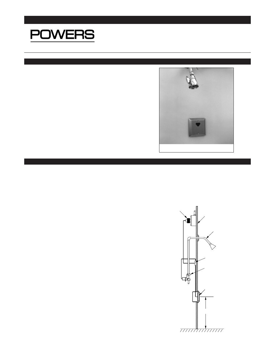
INSTALLATION
Modular
junction box
Sensor
assembly
CL of electrical box:
41
″
to finished floor
Electrical box
(supplied by others)
Solenoid valve
assembly
Finished
wall
Box transformer
41
″
Figure 1: Typical Shower Installation
Showerhead &
arm/flange
Piping supplied
by others
ESP Model 447-10000K100
Form TI447S