Installation instructions – Brandmotion FDMC-1210 User Manual
Page 8
INSTALLATION INSTRUCTIONS
1210 Instructions 6-27-14.docx
Page 8 of 12
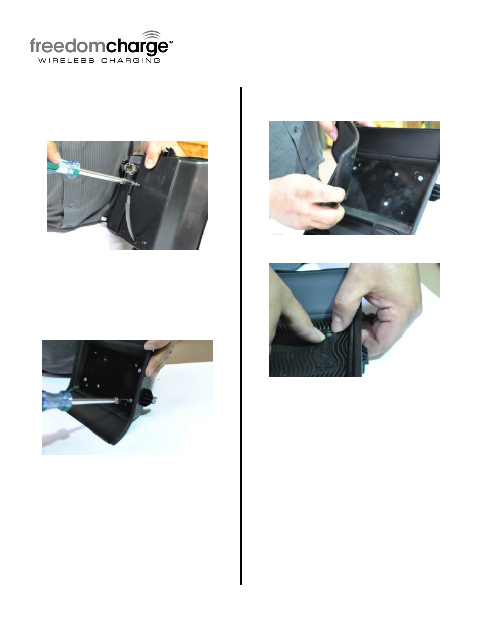
Step 19: Route Plug of Charging Module
through 1/2" hole and place module in bin.
Flip tray over and insert the (2) 3/8” Pan
Head T-20 Torx Screws through tray into
module.
Step 20: From the topside insert the
remaining (2) 1/4" flat head screws through
the substrate and into the modules. Unscrew
the other (2) previously inserted ¼” flat
head screws and repeat steps 17 through 19.
Then replace the remove ¼” flat heads
screws.
Step 21: Install Non-Slip Freedom Charge
Mat to Wireless Charging Module. Place the 4
locator pins in corresponding holes.
Step 22: Firmly press Mat around LED.
Step 23: Proceed to Power Harness wiring
(Section 5).
- 1008-9527-V1 (18 pages)
- 1008-9527-V2 (38 pages)
- 9002-1010 (8 pages)
- 9002-9503-V1 (2 pages)
- 9002-9503-V2 (12 pages)
- 1008-9520-V1 (2 pages)
- 1008-9520-V2 (34 pages)
- 9002-8836 (7 pages)
- 1013-9530-V1 (2 pages)
- 1013-9530-V2 (16 pages)
- 1009-9518 (7 pages)
- 1009-9517 (18 pages)
- 9002-1015 (6 pages)
- 9002-8522 (6 pages)
- 9002-8525 (5 pages)
- 9002-8523 (7 pages)
- 9002-8524 (5 pages)
- 9002-8521 (5 pages)
- 9002-8520 (4 pages)
- 9002-9651 (2 pages)
- 9002-9650 (2 pages)
- 9002-9511 (4 pages)
- 9002-9516 (3 pages)
- 9002-6014 (1 page)
- 9002-9510-V1 (3 pages)
- 9002-9510-V2 (3 pages)
- 9002-9618 (2 pages)
- 9002-9515 Installation Instructions (2 pages)
- 9002-9515 Wiring Instructions (2 pages)
- 9002-9608 (2 pages)
- 9002-9613 (2 pages)
- 1110-2519 (2 pages)
- 9002-9702 (1 page)
- 9002-9703 (2 pages)
- 1110-2518 (2 pages)
- 9002-9704 (1 page)
- 9002-9701 (1 page)
- FLTW-7604 (2 pages)
- 9002-7607 (2 pages)
- 9002-7609 (2 pages)
- 9002-7608 (2 pages)
- 9002-7605 (3 pages)
- 9002-7606 (2 pages)
- FLTW-7603 (3 pages)
- 9002-8501 (4 pages)