Installation instructions – Brandmotion FDMC-1210 User Manual
Page 11
INSTALLATION INSTRUCTIONS
1210 Instructions 6-27-14.docx
Page 11 of 12
Section 5: Under Mounting
Follow the next step if are mounting in a
shallow location or have adequate room and
accessibility under your surface you are
mounting to. Minimum clearance is 5/8”
under mounting location and clear of any
vehicle wiring of components prior to
installation.
Step 32: Using template created in Section 2
to mark the (4) mounting hole, (4) mat
locators and LED locations.
Step 33: Drill (4) 1/8” holes in marked
mounting hole locations and (1) 1/4" hole
for LED. Also drill the (4) 3/16 holes for the
non-skid mat location crosshairs.
Step 34: From top of tray/bin chamfer the
(4) 1/8” holes to allow flat head torx screws
to sit flush.
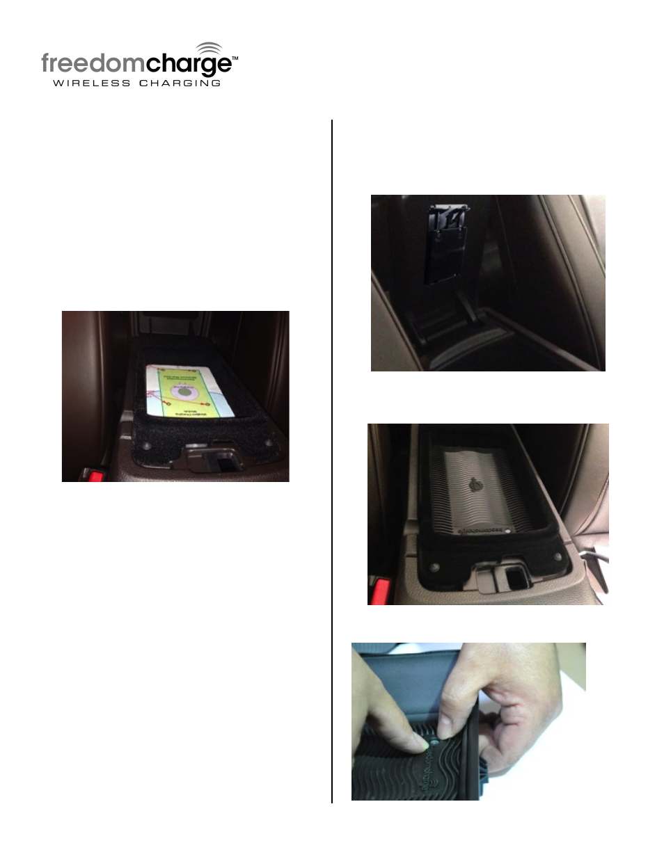
Step 35: From the bottom hold Freedom
Charge Module up firmly into location
allowing the LED to poke through and screw
the (4) 1/2" flat head screws into the module
pulling it snug to tray/bin surface.
Step 36: Place non-skid mat on topside of
tray/bin with the crosshair locators aligned.
Step 37: Firmly press Mat around LED.