Description, Product overview, Figure 1 module architecture – Rockwell Automation T8442 Trusted TMR Speed Monitor User Manual
Page 10: Trusted, Module t8442
Trusted
TM
Module T8442
Issue 8 Apr 10
PD-T8442
10
1. Description
1.1. Product Overview
This section gives a brief overview of the input to output architecture of the T8442 Speed Monitor
Module showing the methods that are employed to achieve fault tolerant operation.
Diagnostics
Diagnostics
Diagnostics
Diagnostics
Diagnostics
Diagnostics
Diagnostics
Diagnostics
Diagnostics
Diagnostics
Diagnostics
SPEED
INPUT
(Slice A)
1
SPEED
INPUT
(Slice B)
1
SPEED
INPUT
(Slice C)
1
PROCESSOR
(Slice A)
1
PROCESSOR
(Slice B)
1
Diagnostics
PROCESSOR
(Slice C)
1
OUTPUT
(Quad 3)
1
OUTPUT
(Quad 4)
1
OUTPUT
(Quad 1)
1
RELAY
(Quad 4)
1
Normally
Energised
LOAD
Normally
DeEnergised
LOAD
SPEED
TRANSDUCER
OUTPUT
(Quad 2)
1
RELAY
(Quad 3)
1
RELAY
(Quad 1)
1
RELAY
(Quad 2)
1
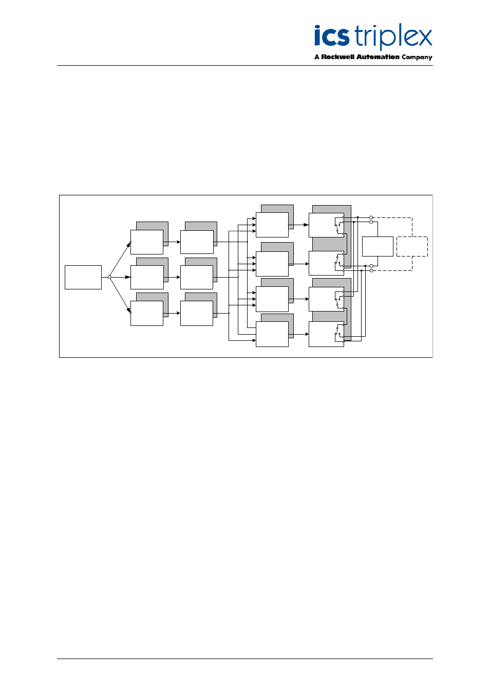
Figure 1 Module Architecture
The T8442 utilises a hybrid redundant architecture to achieve fault tolerant speed sensing and output
control. Critical circuits use either triple or quad redundancy depending on function.
Figure 1 shows the triple and quad arrangements and their associated functions with respect to the
Input to Output signal path.
Each speed transducer input signal from the T8846 SIFTA feeds three identical triple redundant input
circuits on the module.
Diagnostics allow on-line injection of a self-test signal. This is used to verify the speed input circuit
functionality even when the external transducer input is steady state or below the minimum detection
level.
The speed signals from the input circuits are processed by the triple redundant processing elements to
determine rotational speed and acceleration.
Each of the triple redundant processing elements makes an output control decision based upon a
comparison of the rotational speed data received from the speed input circuits and the safe operating
ceiling parameters for that channel.
The output control signal from each of the triple redundant processing elements drives into all four of
the quad redundant output drive circuits.
Each of the quad redundant output drive circuits either energises or de-energises based upon the
majority voted data received from the three processing elements. The majority voting scheme provides
both fault tolerance and fault detection (2oo3).