20 ma output parameters – Rockwell Automation 1440-VLF02-01RA XM-121 Absolute Shaft Module User Manual
Page 71
Publication GMSI10-UM014D-EN-P - May 2010
Configuration Parameters 63
4-20 mA Output Parameters
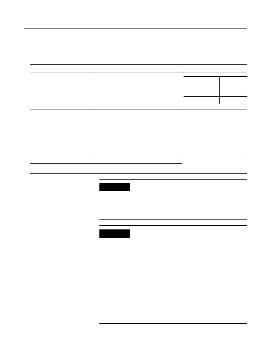
The 4-20 mA output parameters define the characteristics of the two 4-20 mA
output signals. The parameters are the same for each output.
4-20 mA Output Parameters
Parameter Name
Description
Options/Comments
Enable
Enables/disables the 4-20 mA output.
Measurement
Sets the type of measurement and the channel that
the 4-20 mA output signal will track.
Options: Ch 1 SR Overall
Ch 2 CA Overall
Ch 1 SR 1X Magnitude
Ch 2 CA 1X Magnitude
Shaft Absolute Overall
Shaft Absolute 1X Magnitude
Ch 1 DC Bias
Ch 2 DC Bias
Speed
Min Range
The measured value associated with the 4 mA.
Same measurement unit as Output
Data Unit selection for the specified
channel.
Max Range
The measured value associated with the 20 mA.
XM Configuration
Utility
EDS File
Check to enable
Enabled
Clear to disable
Disabled
IMPORTANT
Measured values between Min Range and Max Range are
scaled into the range from 4.0 to 20.0 to produce the
output value. The Min Range value does not have to be
less than the Max Range value. If the Min Range value is
greater than the Max Range value, then the output signal
is effectively inverted from the input signal.
IMPORTANT
The 4-20 mA outputs are either on or off. When they are
on, the 4-20 mA outputs overshoot the 4 and 20 mA limits
by 10% when the measurement exceeds the minimum and
maximum range. This means the minimum current
produced is 3.6 mA and the maximum current produced is
22 mA.
When the 4-20 mA outputs are off, they produce a current
approximately 2.9 mA. The 4-20 mA outputs are off under
the following conditions:
• The 4-20 mA outputs are set to "Disable" (see Enable on
the previous page).
• The module is in Program mode.
• A transducer fault or tachometer fault occurs that affects
the corresponding measurement.