Rockwell Automation 1440-VLF02-01RA XM-121 Absolute Shaft Module User Manual
Page 55
Publication GMSI10-UM014D-EN-P - May 2010
Configuration Parameters 47
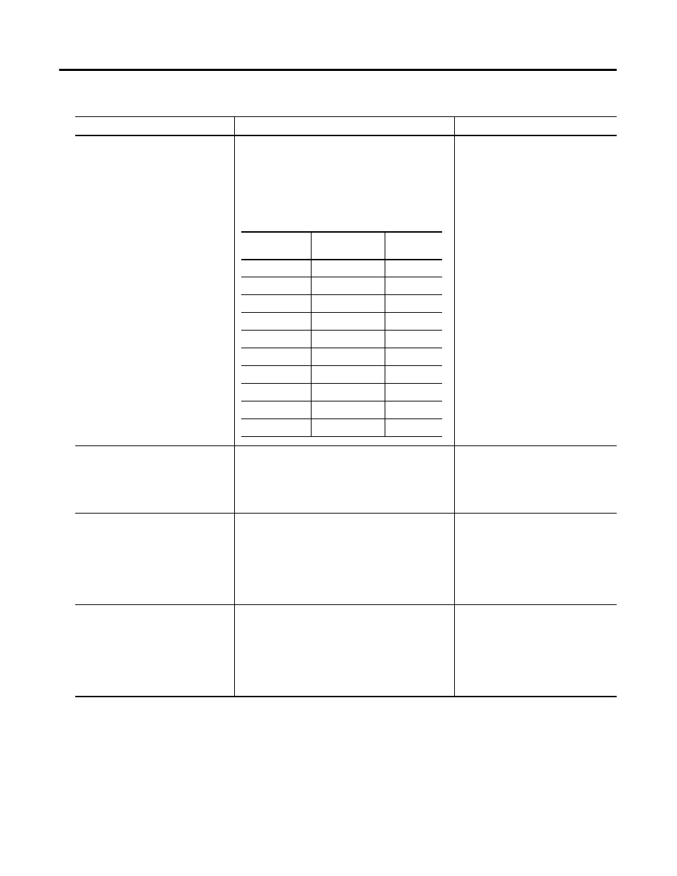
DC Bias Time Constant
The time constant used for exponential averaging
(low pass filtering) of the transducer DC bias
measurement. The corner frequency for the low pass
filter is 1 / (2
π
x DC Bias Time Constant). The
greater the value entered, the longer the settling
time of the measured value to a change in the input
signal. See example table below.
Seconds
Full Scale
The maximum signal level expected to be processed
by the channel. This value is used to determine the
programmable gain settings across each stage of the
channel’s analog signal processing circuit.
Volt
Important: See Appendix D for further
guidance and recommended Full Scale
value settings.
Output Data Units
The data units of the measured values.
Important: The Channel 1 output data units depend
on the units you select for Channel 2. If Channel 2 is
set to "ips" or "mils" then Channel 1 is set to "mils." If
Channel 2 is set to "mm/s or "µm" then Channel 1 is
set to "µm."
Channel 2 Options: mils
ips
mm/s
µm
Autoscale (XM Serial
Configuration Utility only)
Calculates a new Full Scale value based upon the
current input signal level.
Enter a safety factor value greater
than or equal to 1.0.
The safety factor is a number that will
be multiplied to the current signal
level to determine the new Full Scale
setting.
Channel Parameters
Parameter Name
Description
Values/Comments
Time Constant
(seconds)
-3dB Frequency
(Hz)
Settling
(seconds)
1
0.159
2.2
2
0.080
4.4
3
0.053
6.6
4
0.040
8.8
5
0.032
11
6
0.027
13.2
7
0.023
15.4
8
0.020
17.6
9
0.018
19.8
10
0.016
22