Important – Rockwell Automation 1440-VLF02-01RA XM-121 Absolute Shaft Module User Manual
Page 37
Publication GMSI10-UM014D-EN-P - May 2010
Installing the Absolute Shaft Module 29
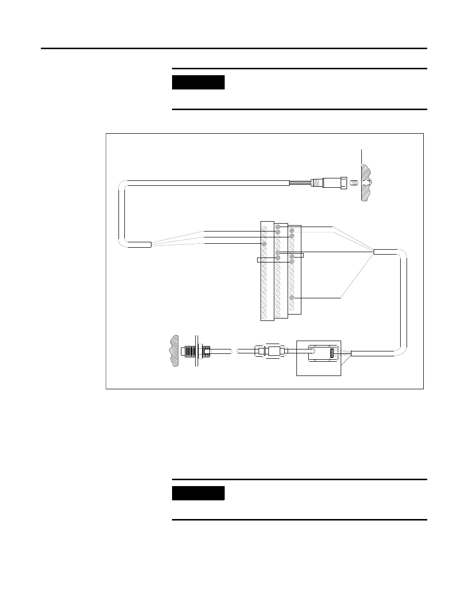
Figure 2.17 Non-Contact Sensor and 9000 Series Sensor Wiring
Connecting Two Non-Contact Sensors and 9000 Series Sensor
The following figure shows the wiring of two non-contact sensors and a 9000
series sensor to the terminal base unit. One non-contact sensor must be wired
to channel 1 and the 9000 sensor must be wired to channel 2. The second
non-contact sensor is wired to the tachometer input signal.
IMPORTANT
Make certain the IEPE Power parameter for channel 2 is
enabled so power is provided to the 9000 sensor. Refer
to Channel Parameters on page 46.
TYPICAL WIRING FOR NON-CONTACT SENSOR AND 9000
SERIES SENSOR TO XM-121 ABSOLUTE SHAFT MODUL E
Shield
Pin A - Signal
Pin B - Common
Cable shield not
connected at this end
0
16
22
6
21
Channel 2 Input Signal
Signal Common
5
37
SIG
-24
COM
17
1
Signal Common
Channel 1 Input Signal
-24V DC
13
Shield
S hield Floating
Isolated Sensor Driver
*
*
*Note: Jumpering terminal 5 to terminal 21
configures CH 1 buffer (-24V to +9V)
Jumpering terminal 6 to terminal 22
configures CH 2 buffer (-5V to +24V)
IMPORTANT
The Absolute Shaft module requires the XM-121 module
revision B01 (and later). Earlier revisions of the module do
not support the Absolute Shaft wiring configuration.