Vector measurement parameters – Rockwell Automation 1440-VLF02-01RA XM-121 Absolute Shaft Module User Manual
Page 59
Publication GMSI10-UM014D-EN-P - May 2010
Configuration Parameters 51
Vector Measurement Parameters
Use these parameters to select and define the filter used to track the machine
speed multiple. The vector measurement parameters apply to both channels.
TIP
The Waveform Period and the Number of Points must
be configured such that the FMAX (Number of
Points/(2.56 x waveform period)) is from 10 Hz to
9375 Hz.
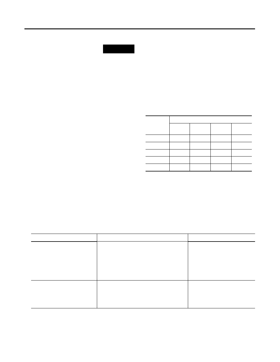
The table below shows some example settings for these
parameters. Note that the Waveform Period may be
rounded up to the next closes period due to available
sampling rates. Combinations that will be rounded are
indicated with an "x".
Table 3.A FMAX for Combinations of Waveform Period &
Number of Points
Number of Points
Period
(seconds)
256
512
1024
2048
0.02
5000
x
x
x
0.2
500
1000
2000
4000
2
50
100
200
400
20
x
10
20
40
80
x
x
x
10
Vector Measurement Parameters
Parameter Name
Description
Values/Comments
Tracking Filter
The type of filter used to track the machine speed
multiple.
•
Bandwidth - The bandwidth of the filter remains
the same at all machine speeds.
•
Q - The ratio of the bandwidth to the center
frequency (machine speed) remains the same.
Options: Bandwidth
Q
Bandwidth
Enter the bandwidth for the Bandwidth filter. The
bandwidth is a measure of the width of a filter.
Enter a value from 0.1 to 25 Hz.
Note: This value is used only when
Bandwidth is selected as the
tracking filter type.