Connecting the transducers – Rockwell Automation 1440-VLF02-01RA XM-121 Absolute Shaft Module User Manual
Page 35
Publication GMSI10-UM014D-EN-P - May 2010
Installing the Absolute Shaft Module 27
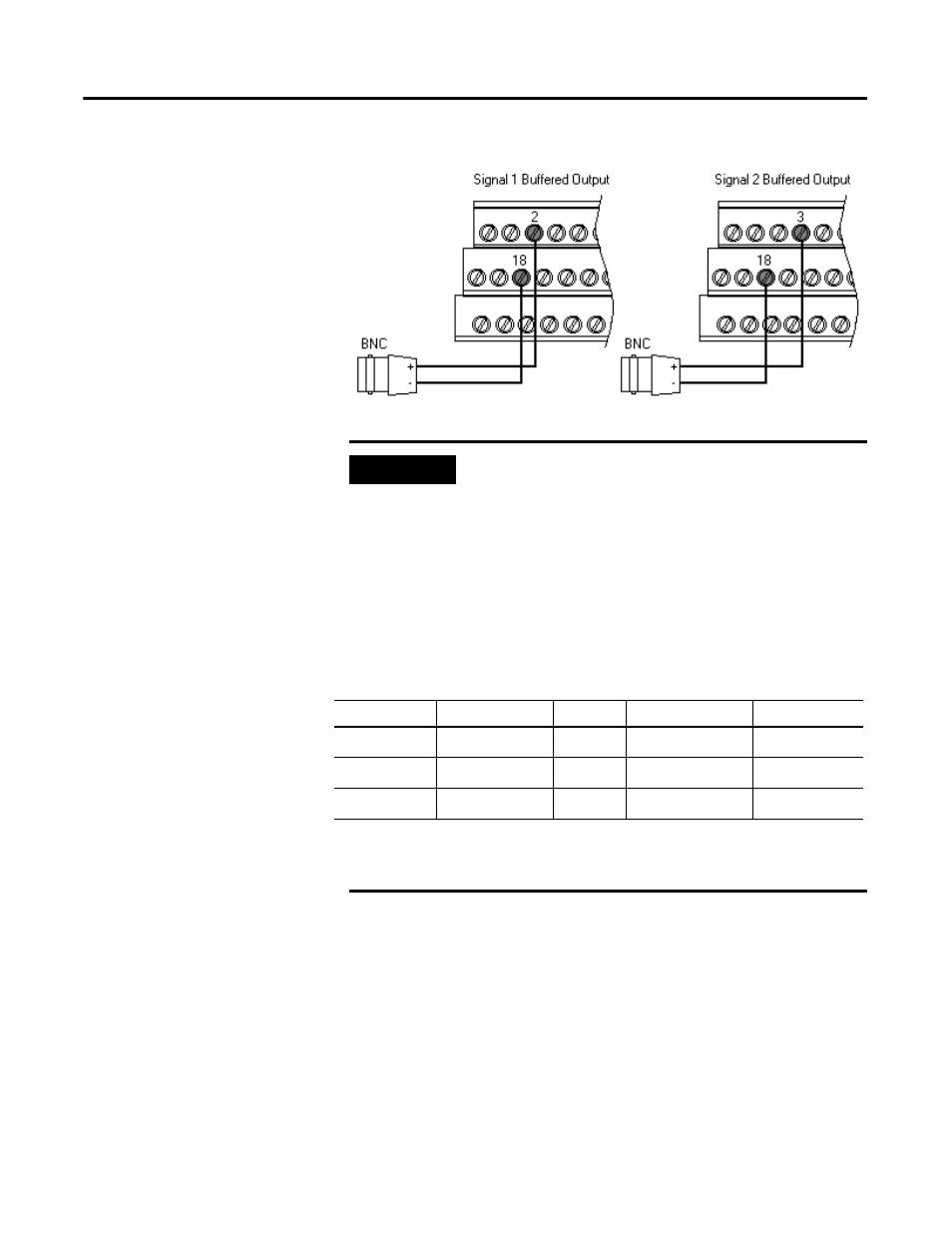
Figure 2.16 Buffered Output Connections
Connecting the Transducers
The Absolute Shaft module can accept input from a non-contact eddy current
probe and a case mounted vibration sensor (accelerometer or velocity sensor).
The signal from a non-contact eddy current probe must be connected to
channel 1. The Absolute Shaft module supports the 5, 8, and 11mm
Allen-Bradley 2100 Series and Bently Nevada 3300 XL Series probes.
IMPORTANT
Applies only to XM-121 module revision B01 (and
later).
The voltage operating range of the buffered outputs must
be configured to coincide with the corresponding
transducer bias range. This operating range is configured by
placing a jumper from terminal 5 (channel 1) and terminal
22 (channel 2) to either terminal 6 (Positive Buffer Bias) or
terminal 21 (Buffer -), depending on the transducer. See
Table 2.2. Note the buffered output operating range is
configured independently per channel.
Table 2.2 Configuring Buffered Output Operating Range
Transducer
Input Range
Channel
Connect Terminal
To Terminal
Negative Bias
1
-24 to +9V
1
5
21
Positive Bias
2
-5 to +24V
2
22
6
Non-Bias
-5 to +9V
2
----
----
1 The signal from the non-contact probe must be connected to channel 1 on the terminal base.
2 The signal from the 9000 sensor must be connected to channel 2 on the terminal base.