Transducer dc bias is monitored on all signals, Important – Rockwell Automation 1440-VLF02-01RA XM-121 Absolute Shaft Module User Manual
Page 38
Publication GMSI10-UM014D-EN-P - May 2010
30 Installing the Absolute Shaft Module
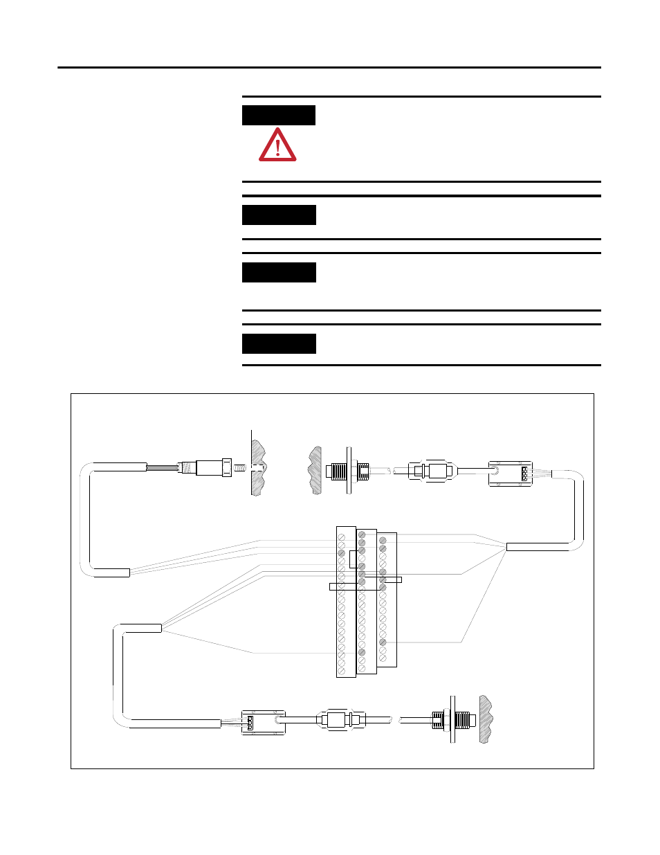
Figure 2.18 9000 Series Sensor and Two Non-Contact Sensors
ATTENTION
You may ground the cable shield at either end of the cable.
Do not ground the shield at both ends. Recommended
practice is to ground the cable shield at the terminal base
and not at the transducer. Any convenient Chassis terminal
may be used (see Terminal Block Assignments on page 18).
IMPORTANT
The internal transducer power supply is providing power to
the non-contact sensor connected to channel 1.
IMPORTANT
Make certain the IEPE Power parameter for channel 2 is
enabled so power is provided to the 9000 sensor. Refer
to Channel Parameters on page 46.
IMPORTANT
Transducer DC bias is monitored on all signals.
TYPICAL WIRING FOR 9000 SERIES SENSOR AND TWO
NON-CONTACT SENSORS TO XM-121 ABSOLUTE SHAFT MODULE
Pin A - Common
Pin B - Signal
Cable shield not
connected at this end
Shield
0
16
Channel 2 Input Signal
Signal Common
SIG
-24
COM
SIG
-24
COM
17
1
Signal Common
Channel 1 Input Signal
21
22
-24V DC
20
-24V DC
4
Signal Common
Tach Input Signal
36
13
31
Shield
Shield
*
* Note: Jumpering terminal 5 to
terminal 21 configures
CH 1 buffer (-24V to 9V)
18
5
6
*
Jumpering terminal 6 to
terminal 22 configures
CH 2 buffer (-5V to +24V)