Of the main circuit, Fig. 3.3-8 – Rockwell Automation Low-Voltage Switchgear and Controlgear User Manual
Page 85
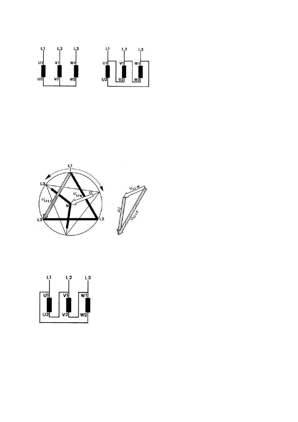
Lower transient currents peaks with correct wiring (clockwise rotation)
Fig. 3.3-8
Correct connection of motor phases for clockwise rotation
During the de-energized switching interval, the rotor falls back against the rotating field of the
power supply. Its magnetic field induces a decaying residual voltage in the stator – in the
voltage phasor diagram
for the pole conductor L1 entered as U
L1’-N
.
When connecting to delta (
L1-L3
is applied to the
stator winding, across which this residual voltage is still present. The differential voltage
∆U is
relatively small, thanks to the favorable vectorial position of the residual voltage U
L1’-N
and the
supply voltage U
L1-L3
that are approximately oriented in the same direction. Thus the current
surge generated by this resultant voltage will also remain small.
Fig. 3.3-9
Phasor diagram for star-delta with correctly connected motor phases for clockwise rotation
High transient current surge with incorrect wiring
The motor also turns clockwise when the terminals are connected according to
Fig. 3.3-10
Incorrect connection of the motor phases also produces clockwise turning
A decaying residual voltage acts again with lagging phase position in the stator during the
switching interval. On switching to delta, the phase winding with the phasor U
L1’-N
is connected
to the supply phase U
L1-L2
. These two voltages however have totally different vectorial direc-
tions, the differential voltage
∆U is high and results in a correspondingly high transient current
surge.
LVSAM-WP001A-EN-P - April 2009
3-9