1 classification and time/current zones, Classification and time/current zones -24 – Rockwell Automation Low-Voltage Switchgear and Controlgear User Manual
Page 132
4.2.1.2.1 Classification
and time/current zones
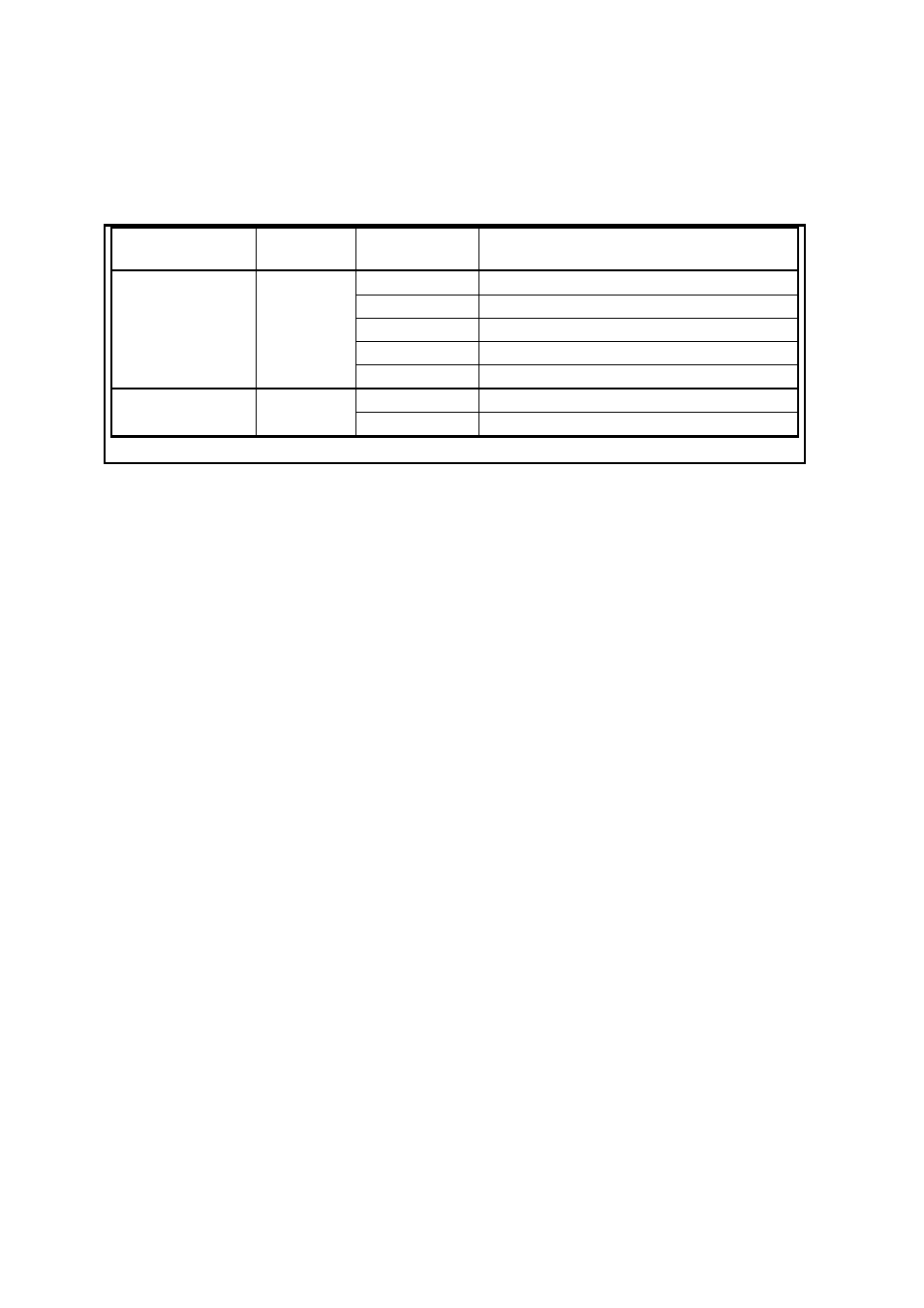
The area of application is designated by two letters, the first of which specifies the breaking
current range and the second the utilization category. A summary of the classification of low-
voltage fuses is provided by
Breaking range
Continuous
load up to
Utilization
category
Characteristic,
Protection of
“gG“ „gL“
Conductors, Cables, Devices
“gM“
Switchgear in motor circuits
“gR“,“ gS“
3)
Semiconductors
“gD“ Fuses
with
time-delay
“g“
1)
I
n
“gN“ Fuses
without
time-delay
“aM“
Switchgear in motor circuits
“a“
2)
I
n
“aR“ Semiconductors
1)
Full-range fuses,
2)
Partial range fuses,
3)
Type “R” is faster than Type “S”
Tab. 4.2-1
Classification of low-voltage fuses according to breaking current range and utilization category
IEC 60269-1 ed. 4.0. Copyright © IEC, Geneva, Switzerland. www.iec.ch.
The letter “g” indicates full-range fuses that can continuously conduct currents at least up to
their rated current I
n
and that can break currents from the smallest melting current up to the
rated breaking current. These include for example “gG” fuses for general applications (cable,
conductor and device protection).
The letter “a” signifies partial range fuses that can continuously conduct currents at least up to
their rated current I
n
and that can break currents above of a certain multiple of their rated current
up to the rated breaking current. This functional class includes for example the “aM” fuses for
protection of motor circuits, whose breaking range begins at over four times the rated current
and which hence are solely designed for short-circuit protection.
Depending on the application requirements, various time/current zones are specified. In
the principal characteristics of time/current zones for the utilization categories “g” and
“a” are presented. The area of the overload curve of fuses of Class “aM” must be protected by
an overload protective device. The release curve of the protective device must be below the
overload curve of the “aM” fuse.
LVSAM-WP001A-EN-P - April 2009
4-24