3 designs, Designs -25, Fig. 4.2-2 – Rockwell Automation Low-Voltage Switchgear and Controlgear User Manual
Page 133
4x10
-3
160
120
60
10
2
1
30
5
10
1
500
100
50
10
4
ms
s
min
-2
10
-1
10
0
10
1
10
2
10
3
10
4
10
s
t
1
2
4
6 8 10
20
40 60 100
I/I
N
Halbleiter aR, gR
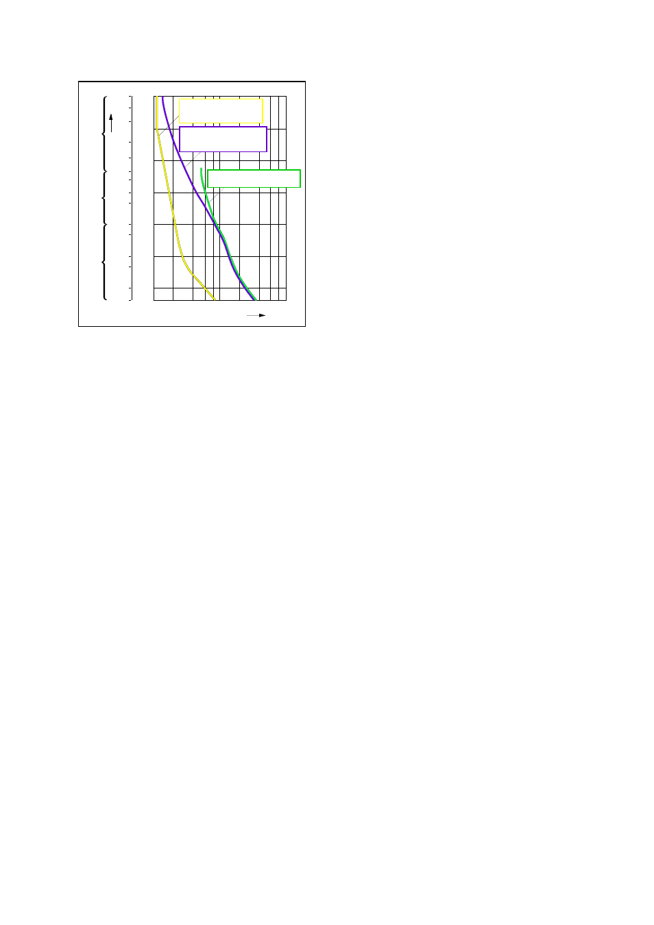
Fig. 4.2-2
Principal characteristics of the time/current zones of fuses
Usually the manufacturers of fuses state these characteristic curves as mean values of a
tolerance band.
Selectivity
The time/current ranges are coordinated for “gG”/“gL” fuses so that fuses whose rated currents
are in the ratio 1:1.6 are usually mutually selective. See also Section
on selectivity.
4.2.1.3 Designs
The design of fuses has developed over time. A distinction is made between designs that are
mainly intended for use by unskilled persons (for example screw-type fuses) and those that are
intended for operation by authorized persons (for example fuses with blade contacts).
Screw-type fuses (for example D System)
The D System is characterized by the non-interchangeability of fuse-links with respect to the
rated current and by their touch protection. They are suitable for industrial applications as well
as for domestic installation and can be operated by unskilled persons. Screw-type fuses are not
suitable for switching operational currents (i.e. they must be screwed in and out without load
current flowing).
Fuses with blade contacts (for example the HRC System)
The HRC system (low-voltage/high rupturing capacity fuse system) is a standardized fuse
system, that consists of a fuse base, a replaceable fuse-link and an operator element for
replacing the fuse-link. HRC fuses can also be equipped with a trip-indicator and tripping
devices.
Non-interchangeability with respect to the rated current and touch protection are not provided;
the HRC system is therefore not suitable for operation by unskilled persons.
Although fuse bases are equipped with phase partition walls and side walls, they are not touch-
safe for fuse replacement. This should therefore only be performed with special protective
equipment. The design sizes of the system have to be indicated with their maximum current
ratings. Within a current range specified by the design size, the use of any fuse rated current is
possible.
Fuse-switch-disconnectors
Safe changing of fuse-links of the HRC system can be achieved by the use of fuse-switch-
disconnectors. The fuse-links are snapped into a cover that covers the entire base and are
Schaltgeräteschutz aM
Kabel- und
Leitungsschutz gG (gL)
Protection of cables and
conductors gG (gL)
Protection of
Semiconductors aR, gR
Protection of switchgear aM
LVSAM-WP001A-EN-P - April 2009
4-25