5 coordination of electrical equipment, Coordination of electrical equipment -12, Example – Rockwell Automation Low-Voltage Switchgear and Controlgear User Manual
Page 40: Fig. 2.3-3, As the time of occurrence of
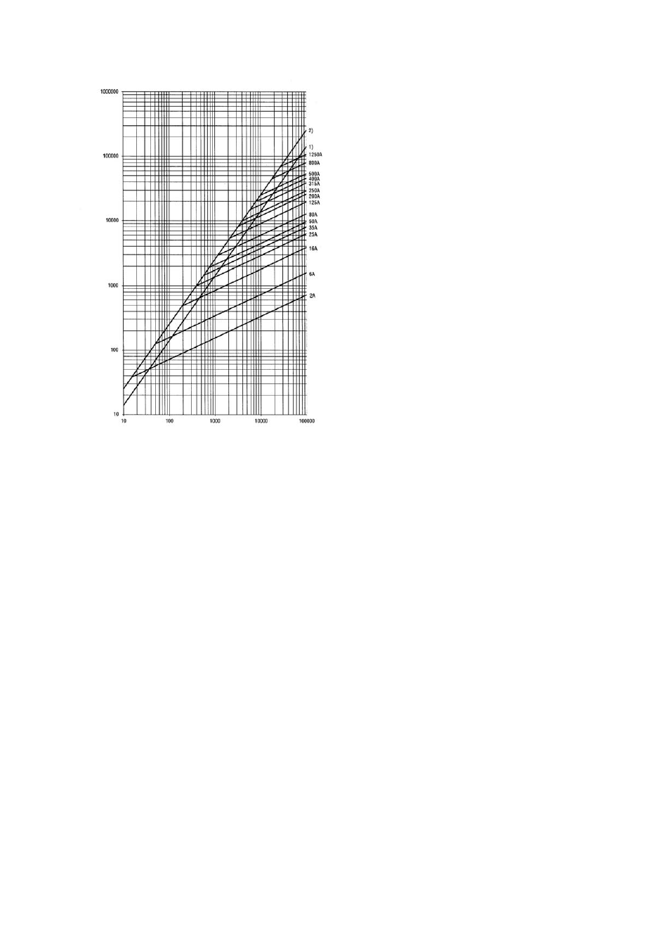
Cut-off current
i
D
[A]
Prospective short-circuit current I
cp
Fig. 2.3-3
Example of an i
D
-diagram for fuses as a function of the prospective short-circuit current I
cp
1) Peak short-circuit current without direct current component
2) Peak short-circuit current with maximum direct current component
2.3.4.5 Coordination
of electrical equipment
The coordination of electrical equipment refers to the assignment of short-circuit protective
devices to contactors or starters with respect to the effects of a short-circuit on these devices.
Distinction is made between two types of coordination:
- The coordination of the trip characteristic of the overload relay (if present) with the protective
characteristic of the short-circuit protective device in respect of the switching capacity of the
contactor
- The coordination between the short-circuit protective device, the contactor and the overload
relay with respect to the destructive effect of a short-circuit and their operability afterward.
2.3.4.5.1
Coordination in respect of the switching capacity of the contactor
(overcurrent selectivity)
The coordination between the release characteristic of the overload relay and the short-circuit
protective device takes account of the switching capacity of the contactor. Contactors are
designed for the operational switching of loads and are not able to switch-off currents of short-
circuit level. The coordination of the devices must ensure that for currents above the switching
capacity of the contactor the short-circuit protective device shuts down before the overload relay
is responding and dropping-out the contactor (
LVSAM-WP001A-EN-P - April 2009
2-12