10 frequency converters, 1 principle of operation, 1 rectifier – Rockwell Automation Low-Voltage Switchgear and Controlgear User Manual
Page 105: Frequency converters -29, Principle of operation -29, Rectifier -29
100%
Percent
Voltage
Time (seconds)
Fig. 3.9-14
Direct start with soft starters. The motor voltage is raised in a short period to the supply voltage.
3.10 Frequency converters
The main area of application of frequency converters with asynchronous motors is operational
speed adjustment and control. In the lower power range of up to a few kW, they are certainly
also to be considered for motor starts as an alternative to soft starters, for reasons of cost and
functionality. Frequently – for example with pump and fan drives – frequency converters are
applied for the optimum control of acceleration and deceleration of the drive as well as for the
operational speed control, for example for energy saving purposes.
For motor starts, frequency converters offer the advantage that in the speed range up to
synchronous speed the full motor torque is available. See also Section
. In addition the
speed characteristic – usually a linear ramp – can be specified and set and is not a given like
with soft starters where it is in a certain range a result of the motor voltage and the load
characteristic (inertial mass and resistive torque).
3.10.1
Principle of operation
The basic mode of operation of frequency converters is explored below. With respect to further
information – for example relating to frequency converters with vector control and slip compen-
sation, inverters with control of the magnetic flux – refer to relevant publications of Rockwell
Automation (see also Allen-Bradley Homepage www.ab.com).
The frequency converter transfers the constant voltage and frequency of the power supply first
into a direct voltage. With this direct voltage it generates a new 3-phase supply for the 3-phase
motor with variable voltage and variable frequency. The frequency converter draws almost only
effective power (cos
φ ~ 1) from the power supply if equipped with an uncontrolled rectifier. The
reactive power required for the motor operation is supplied by the direct voltage intermediate
circuit. Thus in most cases a supply-side power factor compensation device is not required.
shows the schematic diagram.
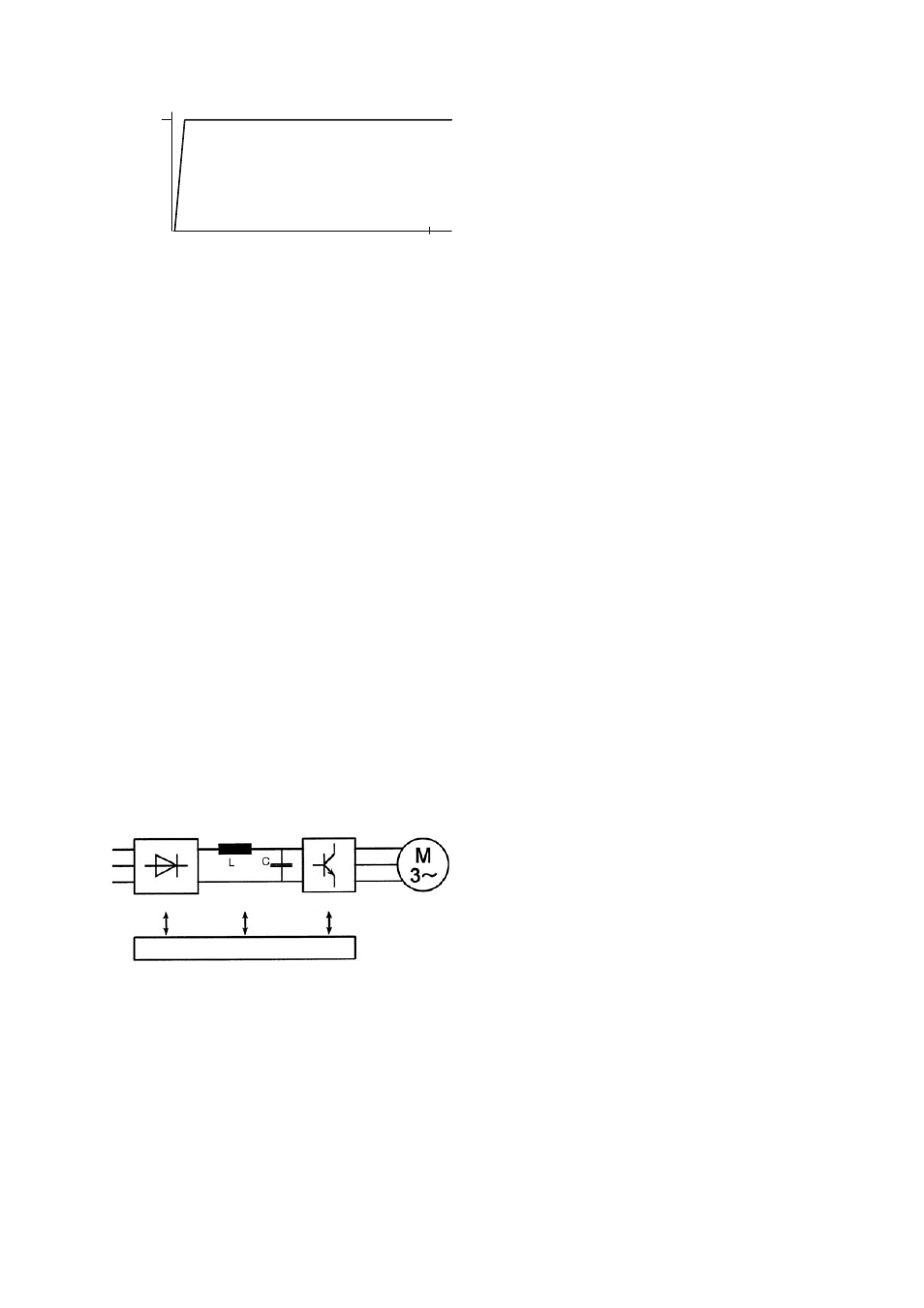
Rectifier Intermediate Inverter
dc-circuit
Control circuit
Fig. 3.10-1
Functional diagram of a frequency converter consisting of rectifier, DC intermediate circuit and inverter
3.10.1.1 Rectifier
The rectifier is connecting to the external supply and generates a direct voltage with ripple,
whose amplitude (with an uncontrolled rectifier) corresponds to the peak value of the connected
supply voltage (U
e
·
√2). For drives with low power ratings (up to approx. 2.2 kW), single-phase
bridge rectifiers are used for cost reasons, for larger power ratings three-phase rectifiers.
LVSAM-WP001A-EN-P - April 2009
3-29