Rockwell Automation Low-Voltage Switchgear and Controlgear User Manual
Page 48
the surrounding components. Serrated edges and loss of contact material toward the arcing
chamber are also normal.
The end of the contact life span is really reached when larger areas of the contact plating have
broken off or there is a danger of the contact touching the substrate material. The below figures
are intended as an aid for an assessment of contacts.
A
A
Sectional
views
A A
B B
B
B
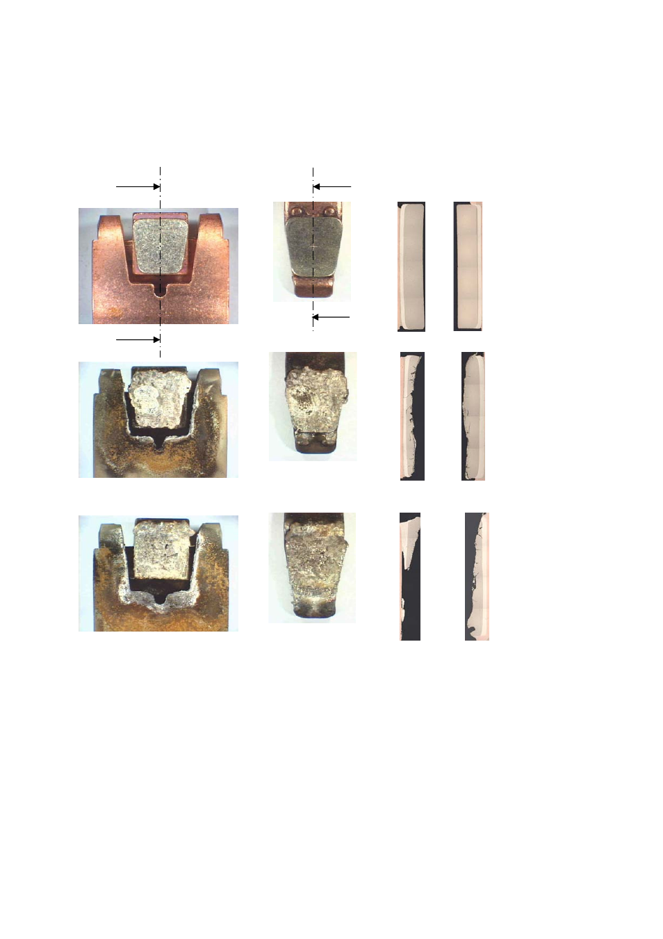
Fig. 2.3-9
Contacts of a power contactor at various stages of the life span with AC-3 loading
Fig.s above:
Contacts in new state
Fig.s in center: Contacts after approx. 75 % of the electrical life span; Contact material partially eroded;
contacts
still
operable
Fig.s below:
Contacts at the end of their life span; Substrate material visible, contact material eroded
down to the substrate; further use would lead to contact welding and excessive tempera-
ture
rise.
The pictures on the right show the contact state in long section. The images of the various life span
phases originate from various contacts, as the contacts can no longer be used once the section has been
cut.
2.3.7
Intermittent and short-time duty, permissible frequency of operation
With continuous duty, i.e. with constant loading over hours, days and longer, the switchgear
reaches its thermal equilibrium. The individual components reach their steady-state tempera-
LVSAM-WP001A-EN-P - April 2009
2-20