Fig. 5.3-3, These – Rockwell Automation Low-Voltage Switchgear and Controlgear User Manual
Page 158
-100
0
100
200
300
400
500
600
700
800
-6
-4
-2
0
2
4
t [ms]
U [V]
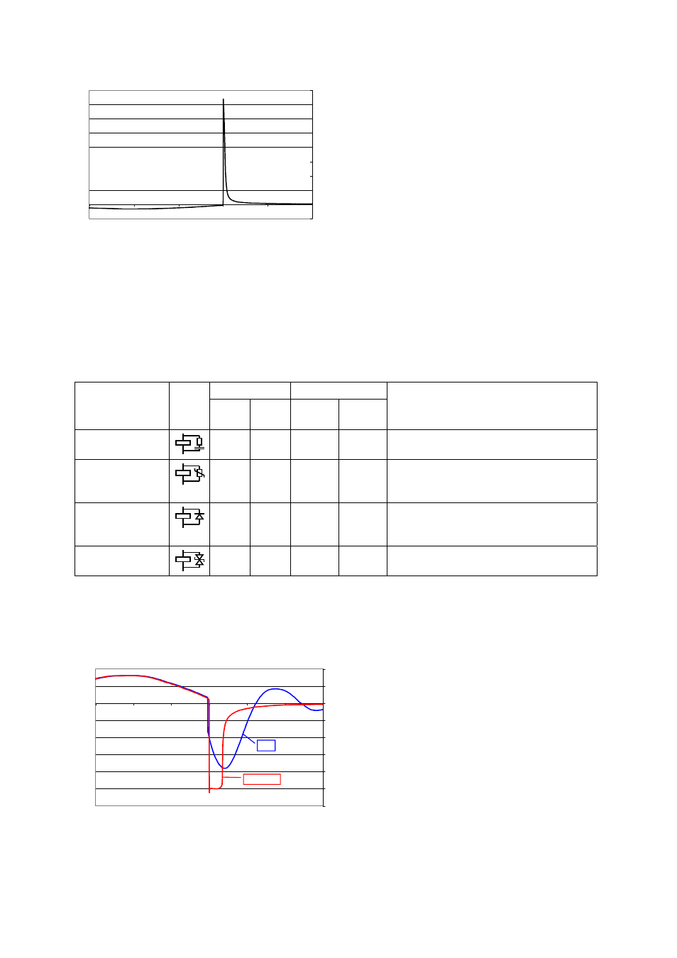
Fig. 5.3-3
Oscillogram of the voltage characteristic during circuit breaking of a 24 V coil without protection circuit
The best countermeasure is to deal with the interference at the source. To this end suppressor
modules are offered for interference-producing coils, designed as plug-on or wired add-ons or
integrated in the contactor.
provides a summary of the alternatives and their most
important features. Measures that only limit the amplitude of the overvoltage are also effective
with respect to dynamic interference (to a limited extent) as they reduce the duration of the
shower discharges and limit their amplitude.
Suitable for
Limitation of
Technical
solution
a.c. d.c. Ampli-
tude
Rise-
time
Functional features
RC module
X
X
X
X
Limitation-effect depends on the
component sizing
Varistor
X
X
X
Amplitude limitation at the operation
voltage of the varistor.
Max. voltage rise Û
C
+U
V
Diode
---
X
X
To be connected with correct polarity.
Extended drop-out time.
Max. voltage rise U
C
Bidirectional
Z-diode
X
X
Small extension of the drop-out time.
Max. voltage rise U
C
+U
Z
Tab. 5.3-1
Protective circuit measures for contactors
U
C
Control
voltage
U
V
Varistor operation voltage
U
Z
Limiting voltage of the Z diode
-120
-100
-80
-60
-40
-20
0
20
40
-6.00
-4.00
-2.00
0.00
2.00
4.00
6.00
t [ms]
U [V]
RC
Varistor
Fig. 5.3-4
Oscillogram of the voltage characteristic during circuit breaking of a 24 V coil with protection circuits
LVSAM-WP001A-EN-P - April 2009
5-6