Install powertap taps – Rockwell Automation DeviceNet Media Design Installation Guide User Manual
Page 65
Publication DNET-UM072C-EN-P - July 2004
Make Cable Connections 3-5
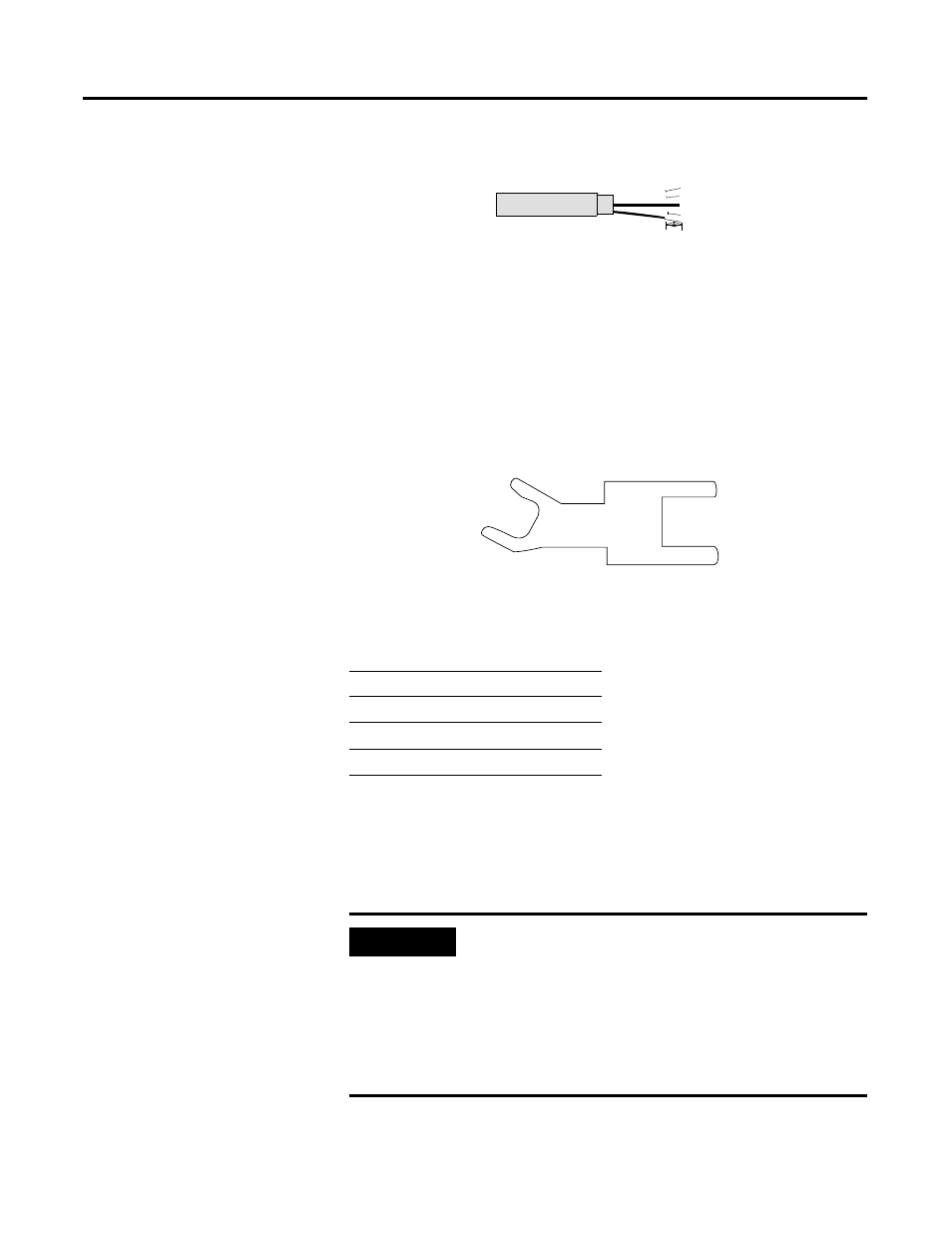
c. Strip 8.1 mm (0.32 in.) of the insulation from the end of each of the
insulated conductors.
3. Attach cables to the enclosure.
a. Loosen the large gland nuts.
b. Insert cables through the large cable glands so that about 3.3 mm
(0.13 in.) of the cable jackets extend beyond the locking nut toward
the inside of the enclosure.
c. Hold the hex flange in place with the cable gland wrench, and firmly
tighten the gland nut. The cable gland wrench is supplied with the
accessories kit, part number 1485A-ACCKIT.
4. Go to the appropriate section.
Install PowerTap Taps
The PowerTap tap contains terminal blocks that connect the trunk line
conductors and the input from a power supply. It is used only with round
media. Gland nuts secure cables to the PowerTap enclosure.
For information about
See page
installing PowerTap taps
3-5
installing DeviceBox taps
3-8
installing DevicePort taps
3-9
8.1 mm
(0.32 in.)
heat shrink
41845
cable gland wrench
20480-M
IMPORTANT
As you make the attachments inside the tap, be certain that:
•
conductors inside the enclosure loop around the fuses
for easy access to the fuses.
•
the bare conductor is insulated in the enclosure with
the insulating tubing supplied in the accessory kit.
•
the blue plastic covers are firmly attached to the fuse
assemblies before applying power.