Rockwell Automation DeviceNet Media Design Installation Guide User Manual
Page 63
Publication DNET-UM072C-EN-P - July 2004
Make Cable Connections 3-3
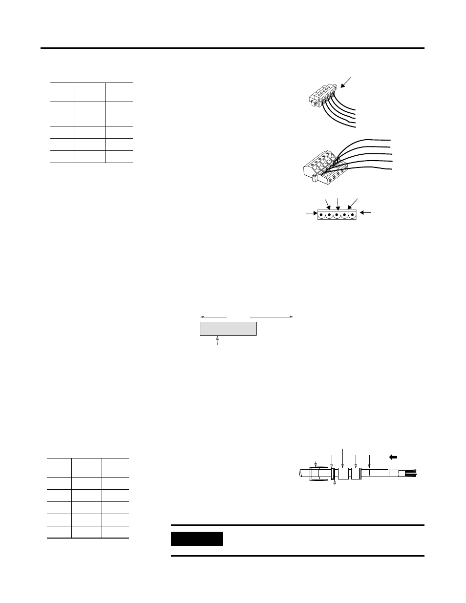
6. Tighten the clamping screws
to secure each conductor.
The male contacts of the
device connector must match
the female contacts of the
connector.
Install Mini/Micro Sealed
Field-Installable
Connectors
To attach a mini/micro sealed-style connector to round media:
1. Prepare the cable jacket by cleaning loose particles from the jacket.
2. Strip 29 mm (1.165 in.) of the cable jacket from the end of the cable.
3. Cut the braided shield and the foil shields surrounding the power and
signal conductors.
4. Trim the conductors to the same length.
5. Slide the connector hardware
onto the cable in the order
shown.
6. Strip 9 mm (0.374 in.) of
insulation from the ends of
all conductors except the
bare drain wire.
30427-M
clamping screws
open-style connector
(female connector)
open-style receptacle
(female contacts)
open-style connector
(female contacts)
red
white
bare
blue
black
red
white
bare
blue
black
black
blue
bare
white
red
Wire
Color
Wire
Identity
Usage
Round
white
CAN_H
signal
blue
CAN_L
signal
bare
drain
shield
black
V-
power
red
V+
power
IMPORTANT
Do not twist or pull the cable while tightening the gland
nut.
jacket
70mm
(2.75 in.)
clean jacket
29 mm
(1.165 in.)
41849
rear nut
grommet
enclosure
slide hardware
bevelled side
Do not nick the
conductor strands.
rubber washer
9 mm
(0.374 in.)
41850
Wire
Color
Wire
identity
Usage
Round
white
CAN_H
signal
blue
CAN_L
signal
bare
drain
shield
black
V-
power
red
V+
power