Rockwell Automation DeviceNet Media Design Installation Guide User Manual
Page 110
Publication DNET-UM072C-EN-P - July 2004
5-6 Correct and Prevent Network Problems
cables
cables are properly routed. Verify that all cables:
•
are kept away from power wiring, as described in publication
1770-4.1
•
are not draped on electric motors, relays, contactors, solenoids, or
other moving parts
•
are not constrained so that cables place excessive tension on
connectors
connectors
connectors are properly installed and are tight. Wiggle connectors to check for
intermittent failures.
scanner
configuration is correct.
1. Verify the scanlist.
2. Check for correct:
•
baud rate
•
node addresses
•
series/revision of the 1747/17711-SDN scanner
3. Cycle power to the 24V dc power supply to reset the scanner and
initialize the network. Then examine scanner display codes to
identify problem nodes. For a listing of scanner display codes, refer
to the documentation shipped with your Rockwell Automation
DeviceNet scanner.
If you see the following at problem nodes, do this:
Solid green (node is allocated by scanner) normal operation; do
nothing
Blinking green (node is not being allocated by the scanner)
•
check that the node is in the scan list
•
check that the scanner is not bus off
•
ensure that the connection is not timing out
Blinking red (no communication)
•
check for missing power on all nodes
•
check all nodes for proper connection to trunk or drop lines
•
check for proper baud rate
•
check scanner for a code 91, which means that communication
with this node has errored out. To reset the scanner, cycle power
to the 24V dc power supply.
Solid red at power up (two nodes have the same address)
Re-assign an available node address.
Solid red at allocation (bus off)
Check for proper baud rate.
If node problems persist, do the following:
•
replace T-tap
•
check topology
•
use an oscilloscope or power disturbance analyzer to check for
electrical noise
•
replace the node. Set the node address and baud rate on the
replacement node, if necessary.
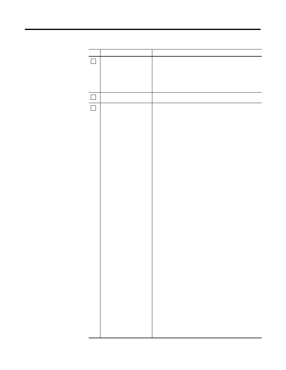
Table 5.1 Troubleshooting your system design
check
to ensure that