Setting up the panelview 1400e terminal, Cutout – Rockwell Automation 2711E-xxxx PanelView Operator Terminals User Manual User Manual
Page 69
4–7
Installing PanelView 1400e Terminals
Publication 2711E-821 – January 1998
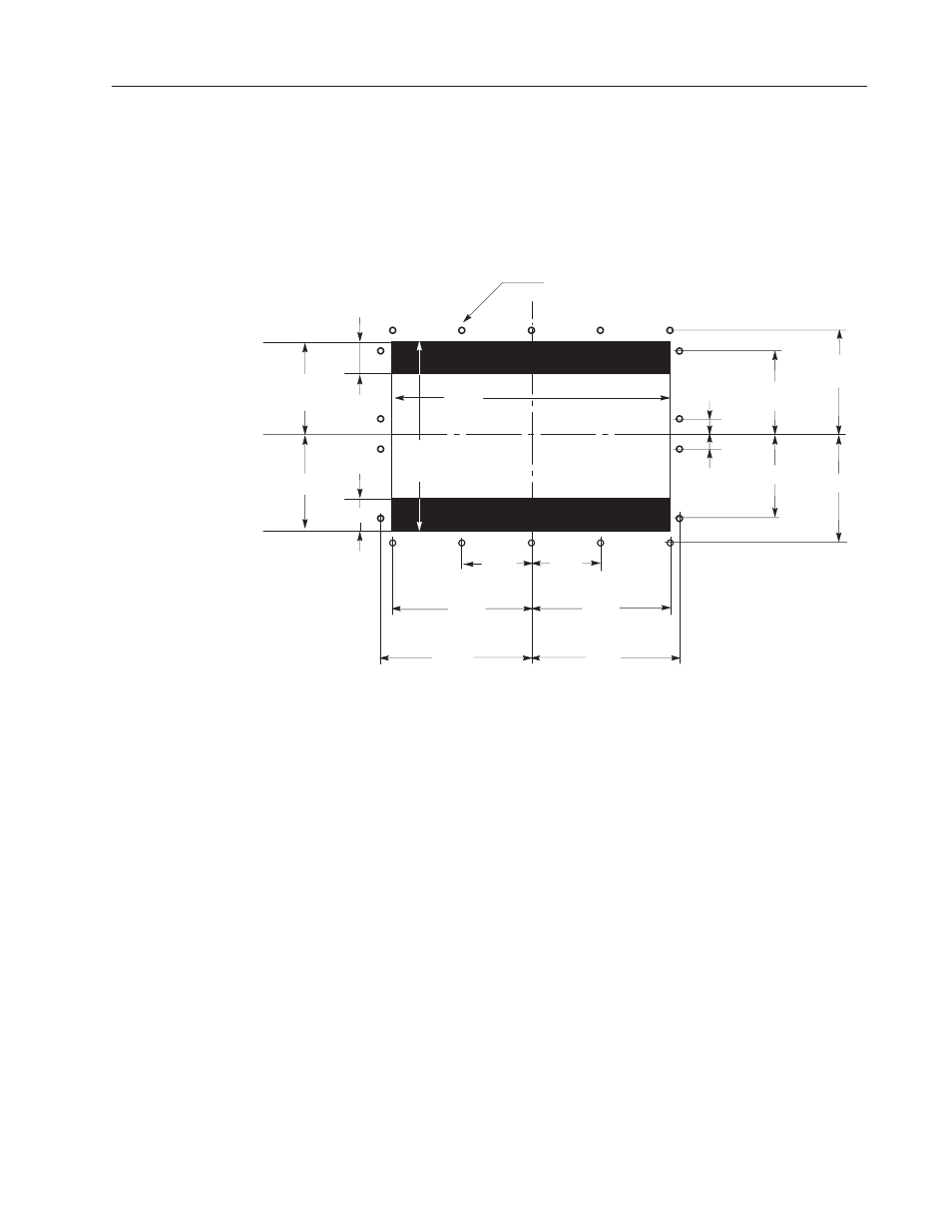
Mounting Your Keypad Terminal in a T30 Cutout
Cutouts made for T30 devices require modification before accepting
the 1400e terminal. Figure 4.6 shows the required changes.
Figure 4.6 Modification to T30 Panel Cutout for 1400e
Keypad Terminals
CUTOUT
C
1.50
I
(38 mm)
5.50
I
(140 mm)
1.50
I
5.50
I
6.70
I
6.70
I
(170 mm)
4.35
I
(110 mm)
4.35
I
8.70
I
(221 mm)
8.70
I
9.16
I
(233 mm)
9.16
I
20183
12.85
I
(326 mm)
16.90
I
(429 mm)
CUTOUT
L
CUTOUT
CL
6.43
I
(163 mm)
1.08
I
(27 mm)
7/32
I
(5.56 mm) DIA. TYP. 18 PLACES
MOUNTING STUDS ARE #10–32 SIZE
6.43
I
1.08
I
There are several controls and connectors to consider when setting
up the terminal. Figure 4.1 shows the locations of the controls and
connectors described in the remainder of this chapter.
Adjusting Contrast and Brightness
The Contrast and Brightness Controls adjust the terminal display
intensity and contrast. The terminal display is set at the factory.
To increase terminal contrast and brightness, turn the controls
clockwise. To decrease terminal contrast and brightness, turn the
controls counter-clockwise. See Figure 4.1.
Adjusting Horizontal and Vertical Position
For any further adjustments, turn the horizontal and vertical knobs
on the side of the terminal, as shown in Figure 4.1.
Setting Up the PanelView
1400e Terminal