Specialty i/o data mapping, 2085-irt4 i/o data mapping – Rockwell Automation 2085 Micro800 Discrete and Analog Expansion I/O Modules User Manual
Page 69
Rockwell Automation Publication 2080-UM003A-EN-E - March 2013
61
Expansion I/O Data Mapping Appendix B
Specialty I/O Data Mapping
2085-IRT4 I/O Data Mapping
Analog input values can be read from Global Variables _IO_Xx_AI_yy, where “x”
represents the expansion slot number 1…4 and yy represents the channel number
00…03.
Analog input status can be read from Global Variables IO_Xx_ST_yy, where “x”
represents the expansion slot number 1…4 and yy represents the status word
number 00…02. Individual bits within a status word can be read by appending a
.zz to the Global Variable name, where "zz" is the bit number 00...15.
Status 4
PU
GF
CRC
Reserved
Reserved
E3
E2
E1
E0
S3
S2
S1
S0
Status 5
Reserved
U3
O3
Reserved
U2
O2
Reserved
U1
O1
Reserved
U0
O0
Status 6
Reserved
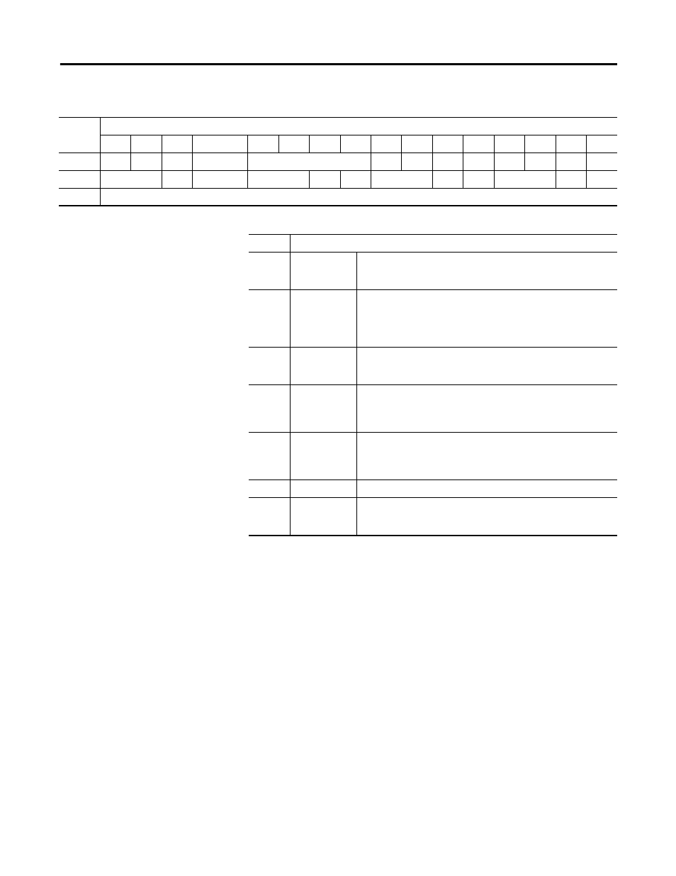
2085-OF4 Status Data Mapping
Word
Bit Position
15
14
13
12
11
10
9
8
7
6
5
4
3
2
1
0
Field Descriptions for 2085-OF4 Status Word
Field
Description
CRC
CRC error
Indicates there is a CRC error on data receive. All channel fault bits
(Sx) are also set. The error is cleared when the next good data is
received.
Ex
Error
Indicates there is an DAC hardware error, broken wire or high load
resistance associated with the channel x, an error code may be
displayed on the respective input word (0…3) and the corresponding
channel is locked (disabled) until user clears the error by writing the
CEx bit in output data.
GF
General Fault
Indicates a fault has occurred, including: RAM test failure, ROM test
failure, EEPROM failure, and reserved bits. All channel fault bits (Sx)
are also set.
Ox
Over-Range
Flag
Indicates the controller is attempting to drive the analog output above
its normal operating range or above the channel's High Clamp level.
However the module continues to convert analog output data to a
maximum full range value if clamp levels are not set for the channel.
PU
Power Up
Indicates an unexpected MCU reset has occurred in RUN mode. All
channel error bits (Ex) and fault bits (Sx) are also set. The module stays
connected with no configuration after the reset. PU and channel fault
bits are cleared when a good configuration is downloaded.
Sx
Channel Fault
Indicates there is an error associated with the channel x.
Ux
Under-Range
Flag
Indicates the controller is attempting to drive the analog output below
its normal operating range or below the channel's Low Clamp level (if
clamp limits are set for the channel).