Rockwell Automation 2085 Micro800 Discrete and Analog Expansion I/O Modules User Manual
Page 31
Rockwell Automation Publication 2080-UM003A-EN-E - March 2013
23
Wiring Connections Chapter 3
6.
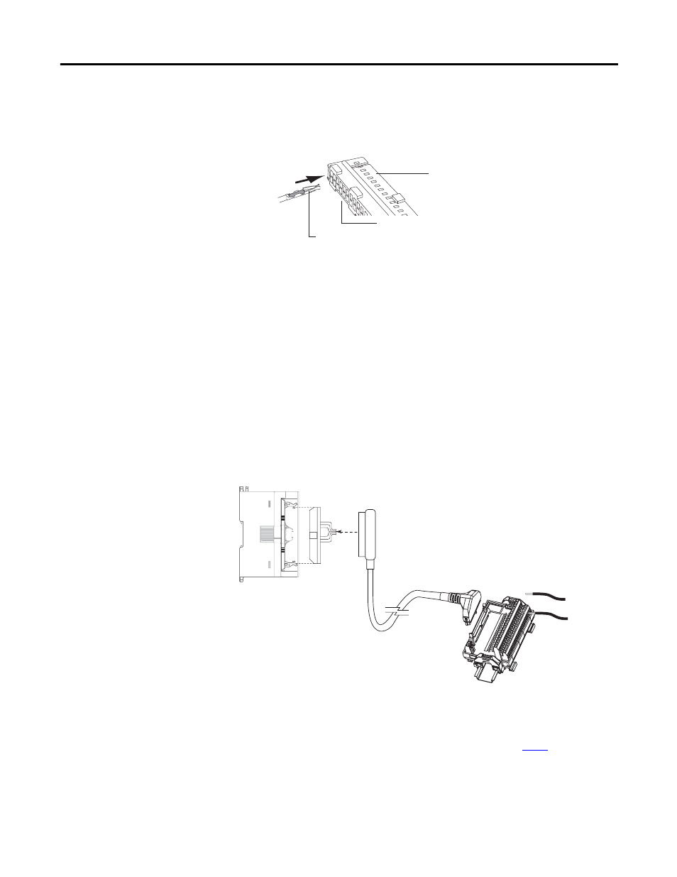
Insert the assembled wire contact into the terminal socket. Push the wire
contact in until the tang latches. Make sure the tang is properly latched by
lightly pulling on the wire.
Option 2 – Use Allen-Bradley 1492 Connector Cables with Flying Leads
Preassembled 40-conductor cables with the 40-pin connector on one end and
flying leads on the other end are also available from Allen-Bradley. They are
available in 1 m, 2.5 m, and 5 m lengths. The catalog numbers from shortest to
longest are:
• 1492-CAB010U62 (or 1492-CAB010P62)
• 1492-CAB025U62 (or 1492-CAB025P62)
• 1492-CAB050U62 (or 1492-CAB050P62)
The “U62” cables route the cable upward when plugged into the module, while
“P62” cables route the cable downward when plugged into the module.
Option 3 – Use Allen-Bradley 1492 Cables with Keyed Connectors
44922
Terminal connector
Terminal sockets
Wire contact
Male
MIL-C-83503
Header
1492-CABLExx
(1)
Connects module
to DIN rail mountable
terminal block
0.32 in. (8 mm) REF.
1492-IFM40xx DIN rail mountable terminal block
24…12 AWG
(0.2…4 mm
2
)
2085-IQ32T Module
46045
(1) Maximum user cable length is dependent on how much voltage drop (current x (ohms/ft.) x (feet)) the user system can
tolerate. The user system should take into account the minimum turn-on voltage required by external loads connected to the
module, the minimum turn-on voltage required by the module, and all of the voltage drops associated with wiring to and
from the load, sensors, terminal blocks, power sources and the module itself. See the table on
page 24
for voltage drop
values for the 1492 cables shown above.