Rockwell Automation 2085 Micro800 Discrete and Analog Expansion I/O Modules User Manual
Page 45
Rockwell Automation Publication 2080-UM003A-EN-E - March 2013
37
Configure Your Expansion I/O Module Chapter 5
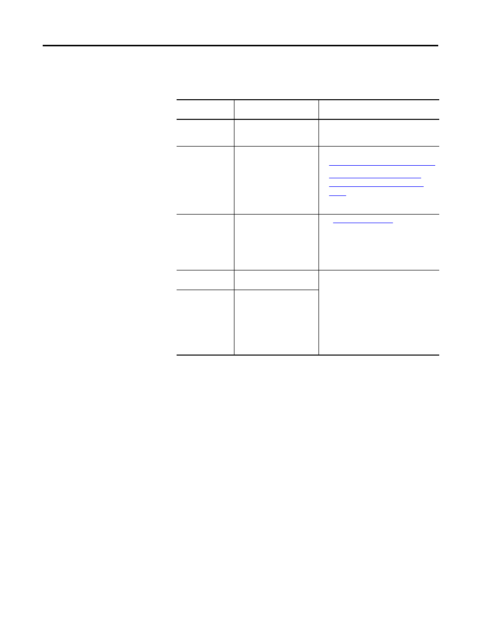
Configuration Parameters for 2085-OF4
Configuration
Property
What to do
Description
Enable channel
Select or deselect the
checkbox. Channel is not
enabled by default.
Enable or disable a channel through this
checkbox. By default, each channel is
disabled.
Minimum-maximum
output range
Choose from a range of
values:
• 0…20 mA
• 4…20 mA (default)
• -10…10 V
• 0…10 V
For more information, see:
•
Input/Output Types and Ranges on page 7
•
Valid Range of the Data Formats for
2085-IF4, 2085-IF8, and 2085-OF4 on
page 8
Data format
Select from the following
options:
• Raw/Proportional Data
• Engineering Units (default)
• Percentage Data
for detailed
information.
High clamp value
Click the checkbox to enable
and enter a high clamp value.
Sets an appropriate alarm that limits the
output from the analog module to remain
within a range configured by the controller,
even when the controller commands an
output outside that range. This safety
feature sets a high clamp and a low clamp.
Once clamps are determined for a module,
any data received from the controller that
exceeds those clamps sets an appropriate
limit alarm and transitions the output to that
limit but not beyond the requested value.
Low clamp value
Click the checkbox to enable
and enter a low clamp value.