Preface – Rockwell Automation 9323-PA2E APS SLC 500 Import/Export Utility User Manual User Manual
Page 59
Preface
APS Import/Export Utility User Manual
5-24
Notice in the preceding example that “0XE000” indicates that control bits EN, TT
and DN are set to one.
Enter the contRol (R) data values in the following order: CTL, LEN and POS. The
import utility does not prevent undefined control bits from being set. Providing data
for undefined control bits does not affect a program.
The control word (CTL) defines the control bits for timers (T), counters (C) and
control (R) file. See tables 5.S, T, and U.
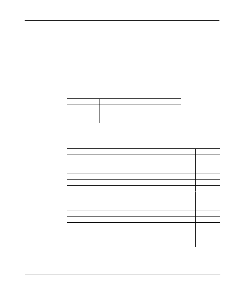
Table 5.S
Control Bits for Timers Defined by the Word CTL
Bit Address
Bit Name
Bit Number
T4:0/EN
Enable
15
T4:0/TT
Timing
14
T4:0/DN
Done
13
Table 5.T
Control Bits for Counters Defined by the Word CTL
Bit Address
Bit Name
Bit Number
C5:0/CU
Counter up enable
15
C5:0/CD
Counter down enable
14
C5:0/DN
Done; accumulator w preset value
13
C5:0/OV
Overflow
12
C5:0/UN
Underflow
11
C5:0/UA
Update accumulator (HSC only)
10
C5:0/HP
Accumulator w hi preset (MicroLogix 1000 controller HSC only)
9
C5:0/LP
Accumulator v lo preset (MicroLogix 1000 controller HSC only)
8
C5:0/IV
Overflow interrupt (MicroLogix 1000 controller HSC only)
7
C5:0/IN
Underflow interrupt (MicroLogix 1000 controller HSC only)
6
C5:0/IH
Hi preset interrupt (MicroLogix 1000 controller HSC only)
5
C5:0/IL
Lo preset interrupt (MicroLogix 1000 controller HSC only)
4
C5:0/PE
User interrupt pending (MicroLogix 1000 controller HSC only)
3
C5:0/LS
User interrupt is lost (MicroLogix 1000 controller HSC only)
2
C5:0/IE
Interrupt enable (MicroLogix 1000 controller HSC only)
1