Rockwell Automation 1747-SN Remote I/O Scanner User Manual
Page 82
Publication 1747-UM013B-EN-P - January 2005
5-4 RIO Block Transfer
RIO Block Transfer Theory of Operation - Block Transfer Write (BTW)
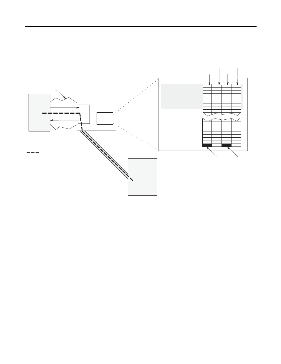
The steps below detail a successful Block Transfer Write (BTW):
1. The user’s control program executes a MOV or COP instruction
to the M0 file to initiate a BTW. The SLC processor sends BTW
data (via the chassis backplane) to the scanner’s M0 block
transfer control and write data file. (See the Block Transfer
Buffer Layout section for details on control information.)
2. The scanner reads the BTW data and control data from the M0
file. One byte of the scanners’s I/O image file is used for
handshake purposes. Note that the SLC user program must
never read or write to this image space.
3. The M1 file contains BTW status information. (See the Block
Transfer Buffer Layout section for details on the status
information.)
4. The RIO scanner transfers BTW information across the RIO link
to the adapter.
5. The adapter transfers the BTW information to the appropriate
adapter or intelligent I/O module.
I/O
Image
Chassis Backplane
RIO Link
= path of the BTW
In this example, Logical Rack 3, Logical Group 7, Logical Slot 1 is used.
M1 file
M0 file
1747 RIO
Scanner
Word 8
Word 9
Word 7
Word 5
Word 6
Word 3
Word 4
Word 1
Word 2
Word 0
Logical
Rack 0
Word 26
Word 27
Word 25
Word 30
Word 28
Word 29
Word 31
Logical
Rack 3
Input Image Output Image
One byte is consumed from the
input and output image file for
handshake purposes.
Group 0
Group 1
Group 2
Group 3
Group 4
Group 5
Group 6
Group 7
Group 0
Group 1
Word 24
Word 23
Group 0
Group 1
Group 2
Group 3
Group 4
Group 5
Group 6
Group 7
Group 7
Slot 0
Slot 1
Adapter or
Intelligent
I/O Module
Slot 0
Slot 1
SLC 5/02
Processor
(or later)
M
Files