Access time – Rockwell Automation 1747-SN Remote I/O Scanner User Manual
Page 116
Publication 1747-UM013B-EN-P - January 2005
B-4 M0 - M1 Files and G Files
Transferring Data Between Processor Files and M0 or M1 Files
The processor does not contain an image of the M0 or M1 file. As a
result, you must edit and monitor M0 and M1 file data via instructions
in your ladder program. For example, you can copy a block of data
from a processor data file to an M0 or M1 data file or vice versa using
the COP instruction in your ladder program.
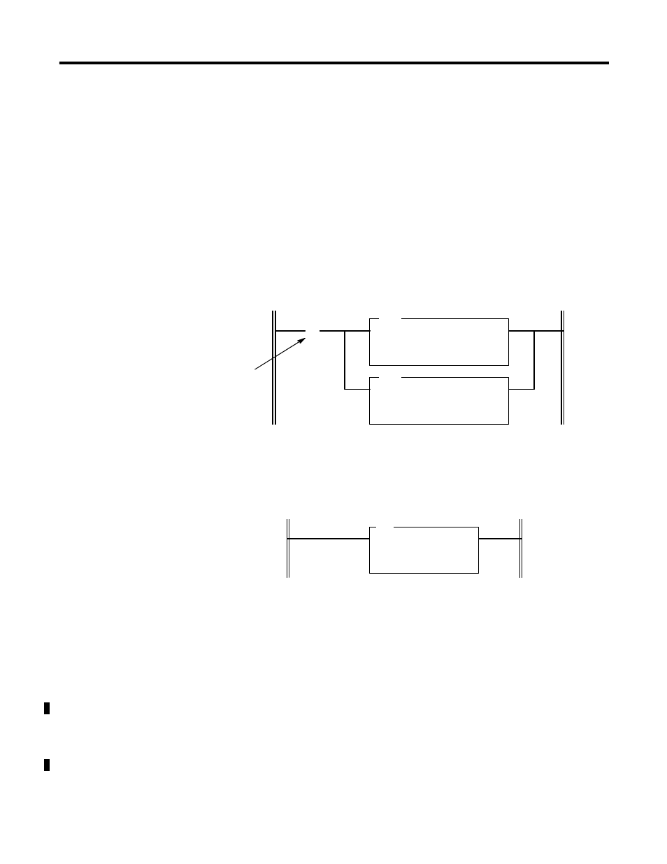
The COP instructions below copy data from a processor bit file and
integer file to an M0 file. For the example, assume the data is
configuration information affecting the operation of the specialty I/O
module.
The COP instruction below copies data from an M1 data file to an
integer file. This technique is used to monitor the contents of an M0 or
M1 data file indirectly, in a processor data file.
Access Time
During the program scan, the processor must access the specialty I/O
card to read/write M0 or M1 data. This access time must be added to
the execution time of each instruction referencing M0 or M1 data. For
the SLC 5/03, SLC 5/04 and SLC 5/05 processors, the instruction types
vary in their execution times.
The following table shows approximate access times per instruction or
word of data for the SLC 5/02, SLC 5/03, SLC 5/04 and SLC 5/05
processors.
COP
COPY FILE
Source #B3:0
Dest #M0:1.0
Length 16
COP
COPY FILE
Source #N7:0
Dest #M0:1.16
Length 27
] [
S:1
15
First scan bit. It makes
this rung true only for
the first scan after
entering Run mode.
COP
COPY FILE
Source #M1:4.3
Dest #N10:0
Length 6