Troubleshooting chapter 7 – Rockwell Automation 1771-PM , D17716.5.18 U MNL 1771-PM CLUTCH/BRAKE MOD User Manual
Page 99
Troubleshooting
Chapter 7
7Ć15
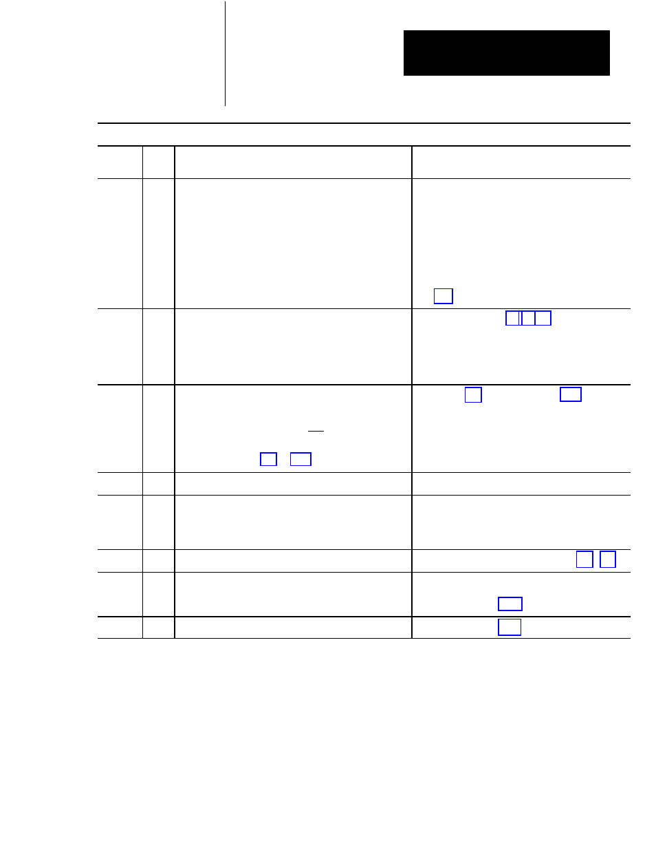
MISCELLANEOUS MESSAGES (cont'd)
HEX
CODE
TYPE
PROBLEM
CORRECTIVE ACTION
0A
N/L
PC ENABLE DROPOUT OR ABSENT
*LATCHED MESSAGE
The PC enable bit from the processor must be maintained to the
PM while in any mode other than off. The PM must also see the
PC enable bit maintained while switching to off mode.
*NON LATCHED MESSAGE
The PM must first see the PC enable bit go on before it sees any
request to change modes. If this does not happen, this message
will occur.
When the PM is actually in the off mode, the PC enable bit
may be turned off.
This condition should be used as a status prompt that
indicates the user program has not given final permission
to enter the selected mode. Check programming in
0B
N
STOPĆONĆTOP SIGNAL FROM PC PREVENTING ENTRY TO
CONTINUOUS MODE.
PM module is still receiving STOPĆONĆTOP command from the
PC processor. This command must be absent before PM can
enter continuous mode.
Check ladder logic (figure 4.6, 4.7, 4.8).
0C
N
AWAITING RELEASE OF INCH BUTTONS FOR ENTERING
INCH MODE.
InchĆbutton inputs must indicate that both inch buttons have
been released, then pushed again before its PM Module will
allow inching motion. This is the anteĆtieĆdown feature of the PM
Module. refer to figures 5.2 and 6.11.
Refer to figure 5.2. Check wiring in figure 6.11.
0D
N
0E
N
PC RUN MODE DROPOUT OR ABSENT
PC processor is not in RUN mode, probably due toa processor
fault.
Correct processor fault. Switch to RUN mode.
0F
N
PRESS INTERLOCK DROPOUT OR ABSENT
Check wiring of press interlock switch in figure 6.1 or 6.5.
10
N
CHECK RUN BUTTON SIGNALS. MAKE STATION ACTIVE OR
BYPASSED.
The cactiveĆstation input is absent, but the PM module is
detecting a changeĆofĆstate of operator RUN buttons.
Check station #1 (figure 6.11).
15
N
MAKE LEFT AND RIGHT ACTIVE CONNECTIONS IDENTICAL. Check station #1 (figure 6.11).