Figure 7.1, Figure 7.a – Rockwell Automation 1771-PM , D17716.5.18 U MNL 1771-PM CLUTCH/BRAKE MOD User Manual
Page 86
Troubleshooting
Chapter 7
7Ć2
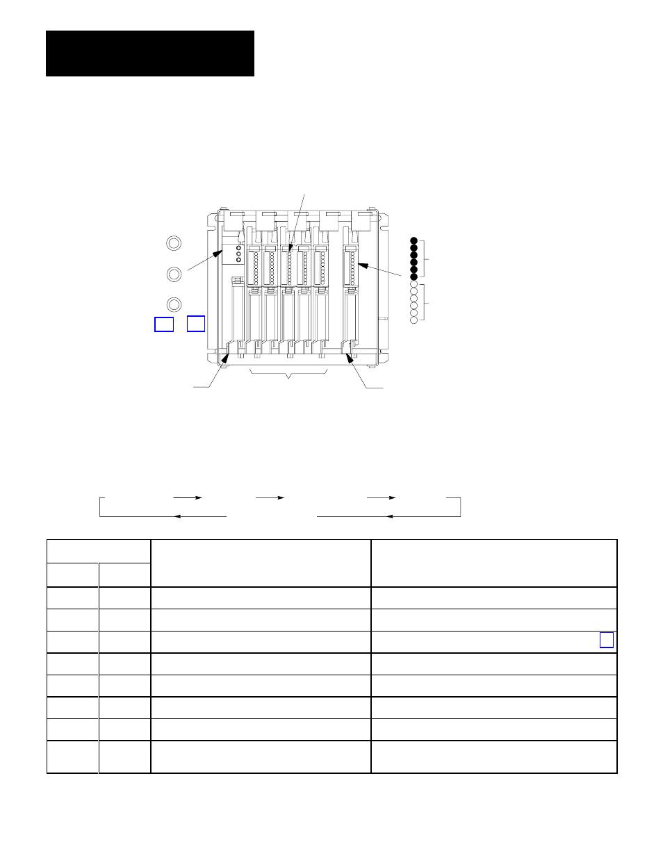
Figure 7.1
Module Indicators for Chassis A or B
12292
ACTIVE
(green)
CBM
FAULT
(red)
I/O RACK
FAULT
(red)
Output status
indicators are red.
On = output
Blown fuse
indicators are clear.
On = blown fuse
Input Module Indicators
Input status indicators are clear. On = input
One indicator per terminal.
1771-PM Module
1771-IA Modules
1771-OD Module
Output Module Indicators
PM Module Indicators
Table 7.A
ACTIVE Indicator
If the ACTIVE indicator is blinking, identify the problem by the number of blinks. There are 2 sets of blinks:
first set of blinks
short pause
second set of blinks
long pause
repeat continuously
Number of Blinks
1st Set
2nd Set
Problem
Correction
1
3
Faulty RAM
Replace 1771ĆPM module
1
4
Faulty PROM
Replace 1771ĆPM module
2
1
Illegal rack address
Set the 1771ĆPM module switches as detailed in chapter 3
2
3
The 1771ĆPM modules contain different firmware
Install 1771ĆPM modules with identical revision codes
3
2
Missing a 1771ĆPM module at power up
Install and fully seat both 1771ĆPM modules
3
4
Illegal interrupt
Cycle power Replace 1771ĆPM module
4
1
Firmware fault
Replace 1771ĆPM module
4
3
Lost communications between 1771ĆPM modules,
or watchdog timed out
Check connections between 1771ĆPM modules or
Replace 1771ĆPM module