Rockwell Automation 1771-PM , D17716.5.18 U MNL 1771-PM CLUTCH/BRAKE MOD User Manual
Page 112
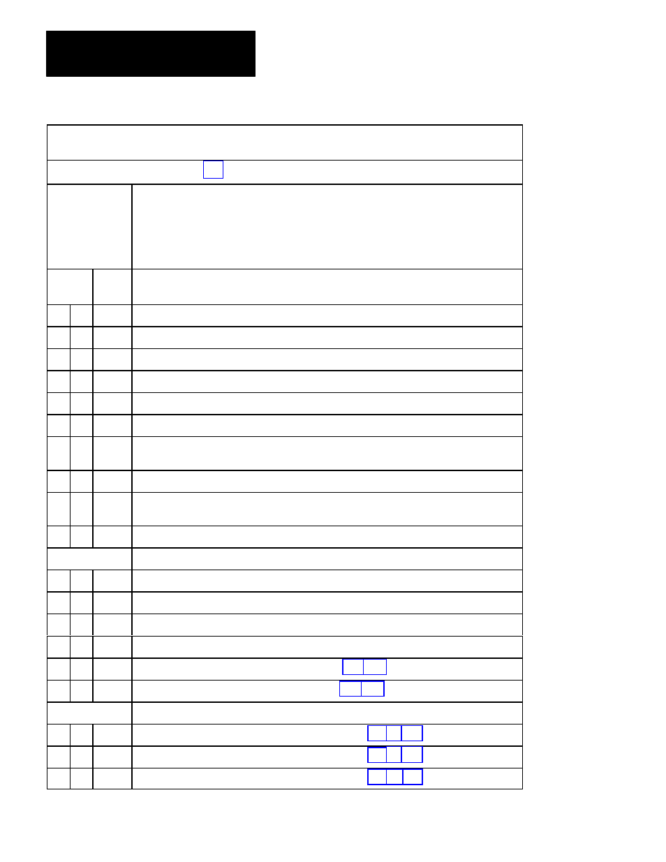
Troubleshooting
Chapter 7
7Ć28
Diagnostic message codes are displayed by indicators connected to module group 5, slot 1 (figure 6.18), or by
displaying the corresponding data table word using the industrial terminal.
Use this table in conjunction with figure 7.1 and figure references shown in parentheses.
Type of Message
N = NonĆlatched
L = Latched
T = Trip
Condition
Code
P = at PowerĆup
Alt = Alternate chassis
Ethr = Either chassis
Top = Top chassis
Bot = Bottom chassis
Hex
Code
Diagnostic Message (figure References)
Type
50
Swingarm power absent
51
N
INCH button not released. Check (NO) contacts.
52 Alt
N
INCH button not released. Check (NO) contacts.
53
N
INCH button not released. Check (NC) contacts.
54 Alt
N
INCH button not released. Check (NC) contacts.
55
P
N
INCH button not released. Check (NC) contacts.
56
P,
Alt
N
INCH button not released. Check (NC) contacts.
57
P
N
INCH button not released. Check (NC) contacts.
58
P,
Alt
N
INCH button is not released. Check (NO) contacts).
59
Not used.
Valve Stem Inputs Not Configured
5A
T
Main valve stem input is present but not configured. (6.17)
5B Alt
T
Main valve stem input is present but not configured. (6.17)
5C
T
Auxiliary valve stem input is present but not configured. (6.17)
5D Alt
T
Auxiliary valve stem input is present but not configured. (6.17)
5E
T
Dump valve stem input is present but no configured. (6.4, 6.9)
5F Alt
T
Dump valve stem input is present but no cinfigured. (6.4, 6.9)
Downstroke Fault
60
L
RUN button in station 1 released too late in the downstroke.(5.3,5.6,6.13)
61
L
RUN button in station 1 released too late in the downstroke.(5.3,5.6,6.13)
62
L
RUN button in station 1 released too late in the downstroke.(5.3,5.6,6.13)