Rockwell Automation 1771-PM , D17716.5.18 U MNL 1771-PM CLUTCH/BRAKE MOD User Manual
Page 110
Troubleshooting
Chapter 7
7Ć26
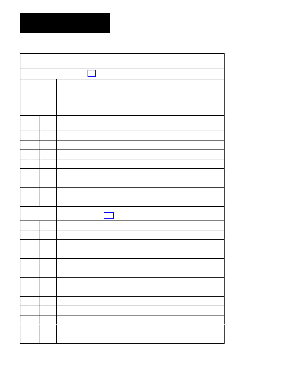
Diagnostic message codes are displayed by indicators connected to module group 5, slot 1 (figure 6.18), or by
displaying the corresponding data table word using the industrial terminal.
Use this table in conjunction with figure 7.1 and figure references shown in parentheses.
Type of Message
N = NonĆlatched
L = Latched
T = Trip
Condition
Code
P = at PowerĆup
Alt = Alternate chassis
Ethr = Either chassis
Top = Top chassis
Bot = Bottom chassis
Hex
Code
Diagnostic Message (figure References)
Type
28
T
Active input changed from closed to open. Check wiring.
29 Alt
T
Active input changed from closed to open. Check wiring.
2A
T
(NC) RUN button bypass is open. Check wiring
2B Alt
T
(NC) RUN button bypass is open. Check wiring
2C
T
(NO) RUN button bypass is open. Check wiring
2D Alt
T
(NO) RUN button bypass is open. Check wiring
2E
Not Used.
2F
Not Used
Station 3
30
N
Check configuration of RUN button signals. Make station active or bypassed
31
N
RUN button not released. Check (NO) contacts.
32 Alt
N
RUN button not released. Check (NO) contacts.
33
N
RUN button not released. Check (NC) contacts.
34 Alt
N
RUN button not released. Check (NC) contacts.
35
P
N
Make left and right active connections identical.
36
P
N
(NC) RUN button is open. Check button or wiring.
37
P
N
(NO) RUN button is shorted. Check button or wiring.
38
T
Active input changed from closed to open. Check wiring.
39 Alt
T
Active input changed from closed to open. Check wiring.
3A
T
(NC) RUN button bypass is open. Check wiring
3B Alt
T
(NC) RUN button bypass is open. Check wiring
3C
T
(NO) RUN button bypass is open. Check wiring