4 compactlogix ladder example program – Rockwell Automation 1769-SM1 Compact I/O to DPI/SCANport Module User Manual
Page 76
6-4
CompactLogix Ladder Example Program
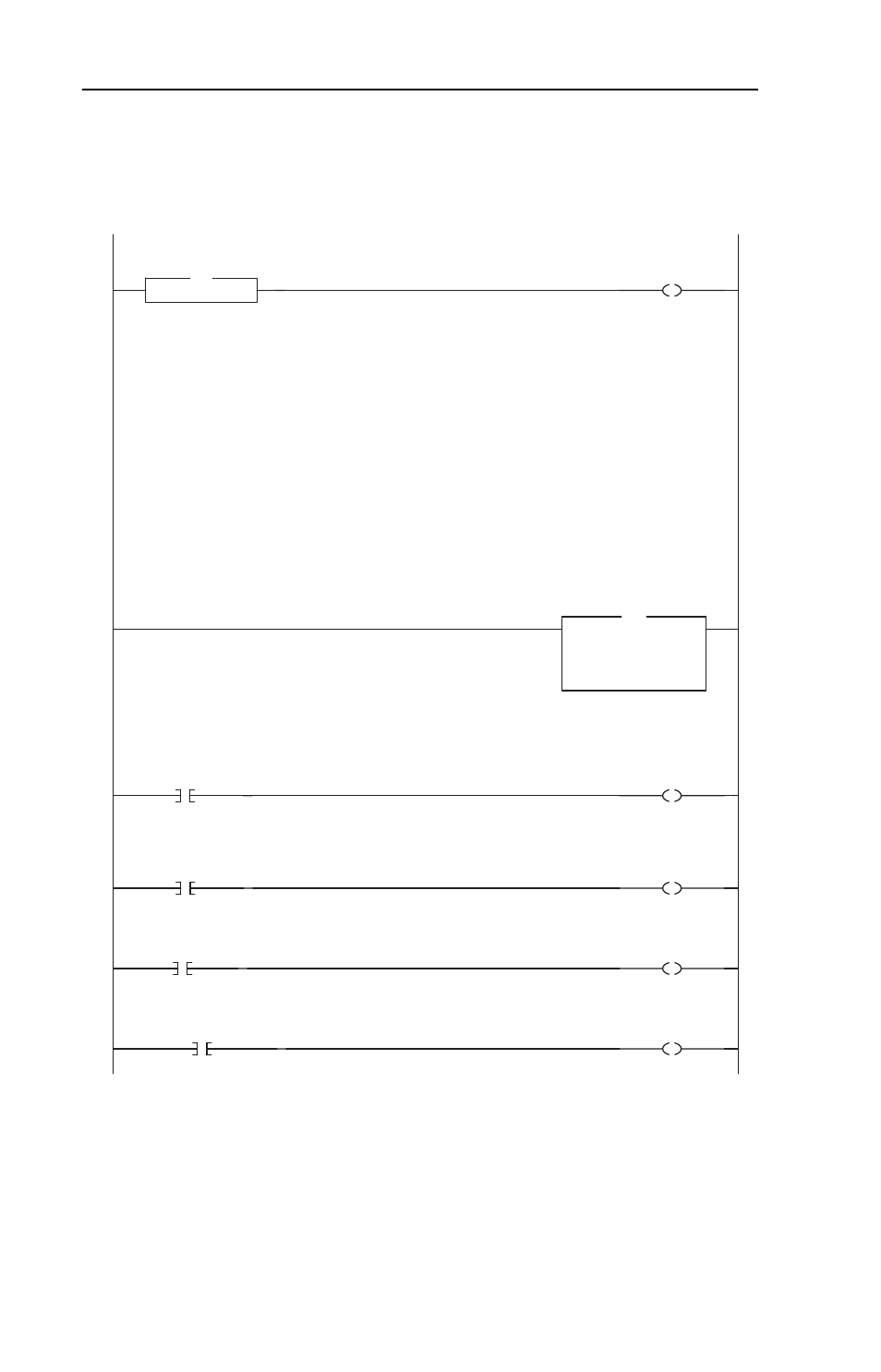
Figure 6.3 CompactLogix Ladder Logic Channel 1 Subroutine
Channel 1 Subroutine
0
Subroutine
SBR
Channel 1
Enable
Local:1:O.Data[0].0
Channel 1 Subroutine
1769-SM1 Channel 1 Status
The bits in the Channel Status word provide status information on the channel itself, where:
bit 00 Logic Status Valid - "1" indicates the Logic Status/Feedback values in the input image are valid
bit 01 Datalink A Out Valid - "1" indicates the Datalink A Out values in the input image are valid
bit 02 Datalink B Out Valid - "1" indicates the Datalink B Out values in the input image are valid
bit 03 Datalink C Out Valid - "1" indicates the Datalink C Out values in the input image are valid
bit 04 Datalink D Out Valid - "1" indicates the Datalink D Out values in the input image are valid
bit 05 not used
bit 06 Configuration Valid - "1" indicates if the configuration is valid (Channel 1 only)
bit 07 Configuration Error - "1" indicates if there is a configuration error (Channel 1 only)
bit 08 DPI/SCANport Port ID bit 0 -
bit 09 DPI/SCANport Port ID bit 1 - these bits indicate the Port # connected to on the Host
bit 10 DPI/SCANport Port ID bit 2 -
bit 11 SCANport Host Present - "1" indicates a SCANport Host is present
bit 12 DPI Host Present - "1" indicates a DPI Host is present
bit 13 32-bit Datalinks Present - "1" indicates 32-bit Datalinks are used
bit 14 32-bit Ref / Fdbk Present - "1" indicates 32-bit Reference / Feedback are used
bit 15 not used
1
Move
Source Local:1:I.Data[0]
0
Dest
SM1_Ch1_Status
0
MOV
Channel 1
Status
1769-SM1 Channel 1 Status
The bits in the Channel Status word provide status information on the channel itself, where:
bit 00 Logic Status Valid - "1" indicates the Logic Status/Feedback values in the input image are valid
bit 01 Datalink A Out Valid - "1" indicates the Datalink A Out values in the input image are valid
bit 02 Datalink B Out Valid - "1" indicates the Datalink B Out values in the input image are valid
bit 03 Datalink C Out Valid - "1" indicates the Datalink C Out values in the input image are valid
bit 04 Datalink D Out Valid - "1" indicates the Datalink D Out values in the input image are valid
bit 05 not used
bit 06 Configuration Valid - "1" indicates if the configuration is valid (Channel 1 only)
bit 07 Configuration Error - "1" indicates if there is a configuration error (Channel 1 only)
bit 08 DPI/SCANport Port ID bit 0 -
bit 09 DPI/SCANport Port ID bit 1 - these bits indicate the Port # connected to on the Host
bit 10 DPI/SCANport Port ID bit 2 -
bit 11 SCANport Host Present - "1" indicates a SCANport Host is present
bit 12 DPI Host Present - "1" indicates a DPI Host is present
bit 13 32-bit Datalinks Present - "1" indicates 32-bit Datalinks are used
bit 14 32-bit Ref / Fdbk Present - "1" indicates 32-bit Reference / Feedback are used
bit 15 not used
Logic Command
2
Ch1_Stop_Command
Channel 1
Logic Command
STOP
Local:1:O.Data[1].0
Logic Command
3
Ch1_Start_Command
Channel 1
Logic Command
START
Local:1:O.Data[1].1
4
Ch1_Jog_Command
Channel 1
Logic Command
JOG
Local:1:O.Data[1].2
5
Ch1_ClearFaults_Command
Channel 1
Logic Command
CLEAR FAULTS
Local:1:O.Data[1].3