Rockwell Automation 1769-SM1 Compact I/O to DPI/SCANport Module User Manual
Page 61
MicroLogix 1500 Ladder Example Program
5-7
Channel 2 and Channel 3 ladder subroutines are similar to the Channel 1
subroutine and are not provided.
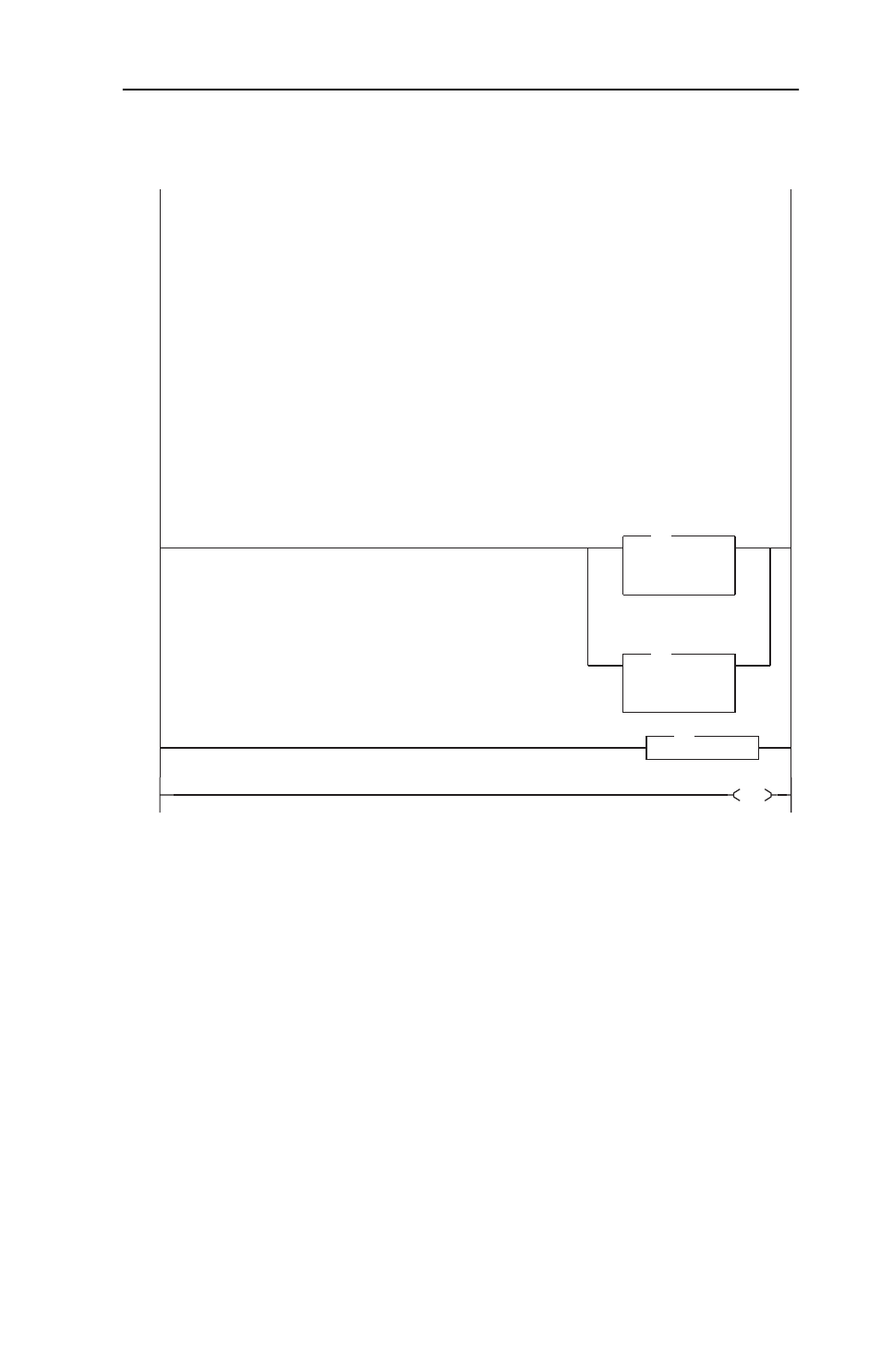
Figure 5.3 MicroLogix 1500 Ladder Logic Channel 1 Subroutine (Continued)
Datalink D Control Area
The first COPy instruction outputs data to Datalink D1 & D2 In, where:
PF70 Parameter 306 [Data In D1] is set to "103", which points to Parameter 103 [Preset Speed 3]
N7:16 contains the Preset Speed 3 value in hertz, where a "300" equates to 30.0 Hz.
PF70 Parameter 307 [Data In D2] is set to "104", which points to Parameter 104 [Preset Speed 4]
N7:18 contains the Preset Speed 4 value in hertz, where a "400" equates to 40.0 Hz.
The second COPy instruction inputs data from Datalink D1 & D2 Out, where:
PF70 Parameter 316 [Data Out D1] is set to "103", which points to Parameter 103 [Preset Speed 3]
N7:36 contains the Preset Speed 3 value in hertz, where a "300" equates to 30.0 Hz.
PF70 Parameter 317 [Data Out D2] is set to "104", which points to Parameter 104 [Preset Speed 4]
N7:38 contains the Preset Speed 4 value in hertz, where a "400" equates to 40.0 Hz.
Note: Datalink D1/D2 Out does not have to equal Datalink D1/D2 In.
This is done in the example program for demo purpose only (so changes can be viewed).
The format is:
N7:x = Datalink D1 (low) value for 16-bit Datalinks, low word for 32-bit Datalinks
N7:x+1 = Datalink D1 (high) high word for 32-bit Datalinks
N7:x+2 = Datalink D2 (low) value for 16-bit Datalinks, low word for 32-bit Datalinks
N7:x+3 = Datalink D2 (high) high word for 32-bit Datalinks
0012
COP
Copy File
Source
#N7:16
Dest
#O:1.48
Length
4
COP
Channel 1
Datalink D1 In
(Low)
COP
Copy File
Source
#I:1.48
Dest
#N7:36
Length
4
COP
Channel 1
Datalink D1 Out
(Low)
0013
RET
Return
RET
0014
END