Viewing the module configuration, Viewing the module configuration 3-18 – Rockwell Automation 1769-SM1 Compact I/O to DPI/SCANport Module User Manual
Page 48
3-18
Configuring the Module
The following parameters provide information about how the 1769-SM1
module is configured. You can view these parameters at any time.
Viewing the Module Configuration
Number Name
Description
01
Config Mode
The configuration mode for the module (Controller or Parameters).
05
Ref/Fbk Size 1
The size of the Reference/Feedback for the CH1 drive (16 bits or 32 bits).
It is set in the drive and the module automatically uses the correct size.
06
Datalink Size 1
The size of each Datalink for the CH1 drive (16 bits or 32 bits). They are
set in the drive and the module automatically uses the correct size.
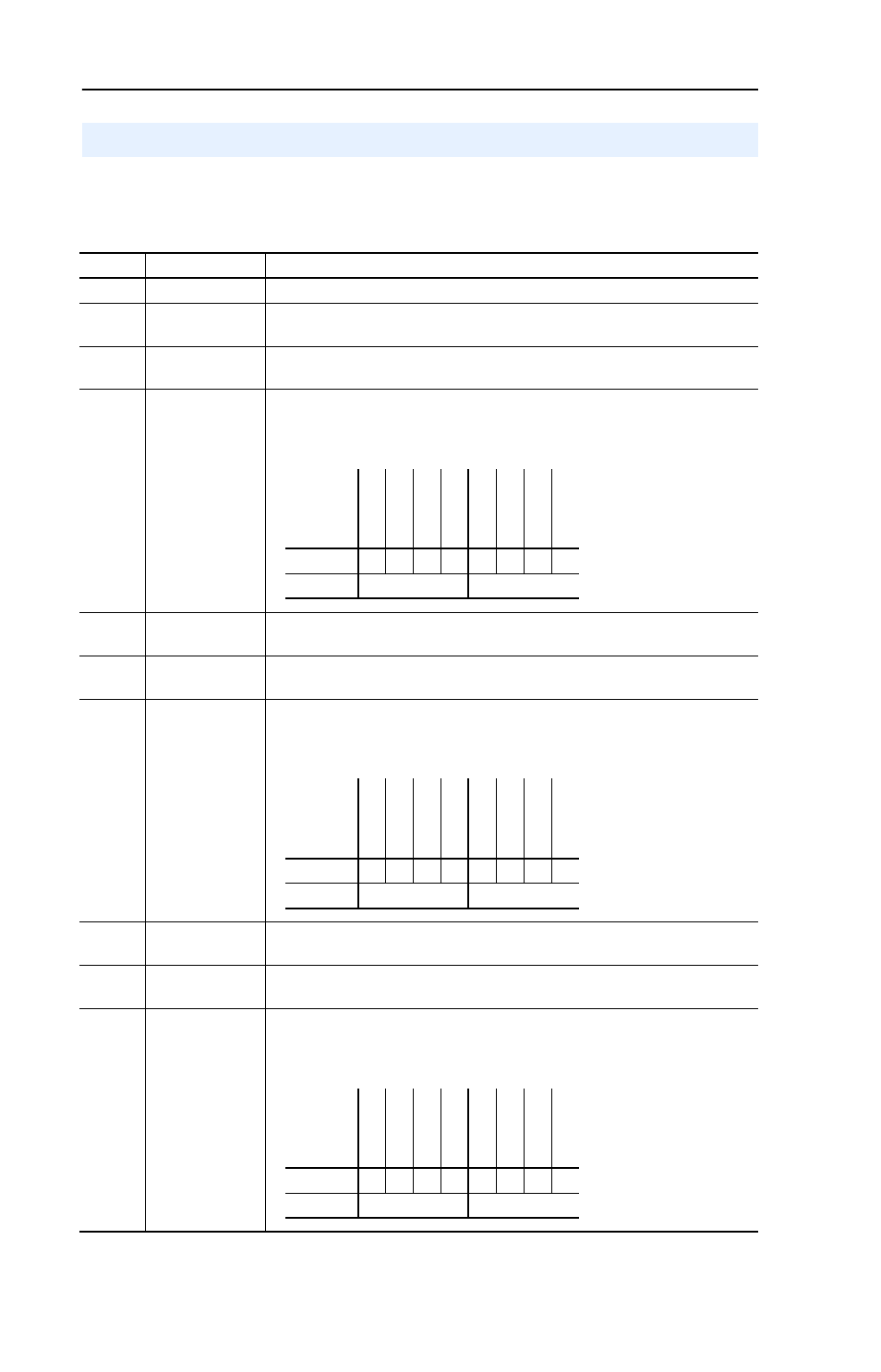
08
I/O Actual 1
The Reference/Feedback and Datalinks used by the module for the CH1
drive. This value is the same as Parameter 07 - [I/O Config 1] unless the
parameter was changed and the module was not reset.
22
Ref/Fbk Size 2
The size of the Reference/Feedback for the CH2 drive (16 bits or 32 bits).
It is set in the drive and the module automatically uses the correct size.
23
Datalink Size 2
The size of each Datalink for the CH2 drive (16 bits or 32 bits). They are
set in the drive and the module automatically uses the correct size.
25
I/O Actual 2
The Reference/Feedback and Datalinks used by the module for the CH2
drive. This value is the same as Parameter 24 - [I/O Config 2] unless the
parameter was changed and the module was not reset.
39
Ref/Fbk Size 3
The size of the Reference/Feedback for the CH3 drive (16 bits or 32 bits).
It is set in the drive and the module automatically uses the correct size.
40
Datalink Size 3
The size of each Datalink for the CH3 drive (16 bits or 32 bits). They are
set in the drive and the module automatically uses the correct size.
42
I/O Actual 3
The Reference/Feedback and Datalinks used by the module for the CH3
drive. This value is the same as Parameter 41 - [I/O Config 3] unless the
parameter was changed and the module was not reset.
Bit
Definition
Not Us
ed
Not Us
ed
Not Us
ed
Da
ta
link
D
Da
ta
link
C
Da
ta
link
B
Da
ta
link
A
Cmd/Sts
Default
x
x
x
0
0
0
0
1
Bit
7
6
5
4
3
2
1
0
0 = I/O disabled
1 = I/O enabled
Bit
Definition
No
t Used
No
t Used
No
t Used
Dat
alink
D
Dat
alink
C
Dat
alink
B
Dat
alink
A
Cmd
/Sts
Default
x
x
x
0
0
0
0
1
Bit
7
6
5
4
3
2
1
0
0 = I/O disabled
1 = I/O enabled
Bit
Definition
Not Us
ed
Not Us
ed
Not Us
ed
Da
ta
link
D
Da
ta
link
C
Da
ta
link
B
Da
ta
link
A
Cmd/Sts
Default
x
x
x
0
0
0
0
1
Bit
7
6
5
4
3
2
1
0
0 = I/O disabled
1 = I/O enabled