Rockwell Automation 1746-HSCE2 Multi-Channel High Speed Counter Module User Manual
Page 91
Publication 1746-UM002B-EN-P - August 2004
Start Up, Operation, Troubleshooting, and Debug Mode 5-9
In the Minimum/Maximum Rate Value Block
For this block, the transmit bit, the debug bit, the block type byte, and
the counter number are required for each configured counter. Word 0
must be used for each configured counter individually. Bits 10, 11, 13,
and 14 must be zero. The values of words 1 through 7 are ignored by
the module while in debug mode.
Figure 5.6 Required Bits for Min./Max. Rate Value Block
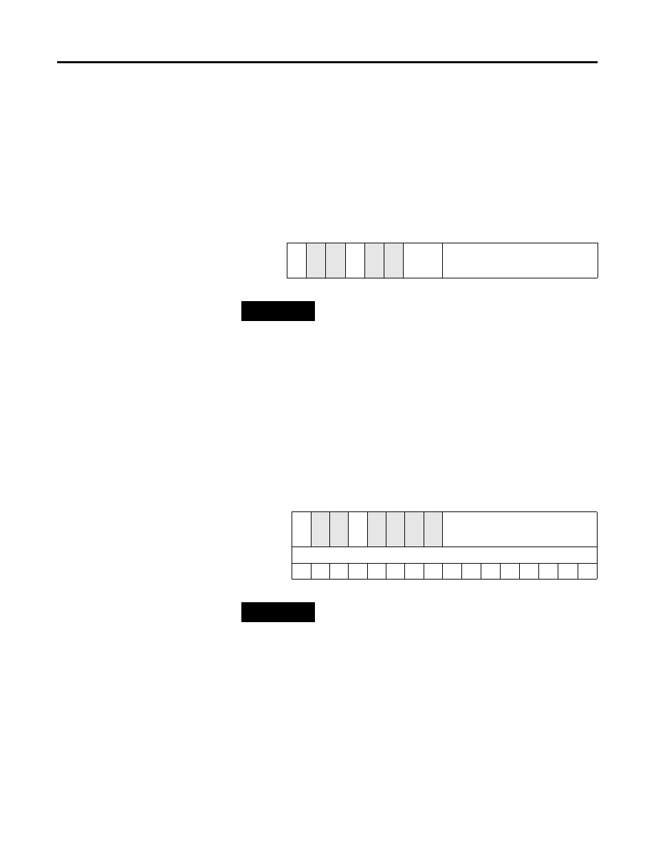
In the Program Ranges Block
To activate the debug mode in the Program Ranges block, the transmit
bit, the debug bit, the block type byte, and the range number word
(word 1, bits 0 - 15) are required for each range individually. The
counter number (word 0, bits 08 and 09) must be zero or a
programming error results. The values of any other bits or words 2
through 7 are ignored by the module while in debug mode.
Figure 5.7 Required Bits for Program Ranges Block
15 14 13 12 11 10 09 08 07 06 05 04 03 02 01 00
Word 0
TRMT
0
0
DEBUG
0
0
CNTR
No.
BLOCK TYPE
TIP
If the counter number entered is not valid, the debug
mode returns a programming error.
15 14 13 12 11 10 09 08 07 06 05 04 03 02 01 00
Word 0
TRMT
0
0
DEBUG
0
0
0
0
BLOCK TYPE
Word 1
Range Number
TIP
If more than one bit in word 1 is set (1), the module
returns a programming error.