Rockwell Automation 1746-HSCE2 Multi-Channel High Speed Counter Module User Manual
Page 39
Publication 1746-UM002B-EN-P - August 2004
Module Operation 2-19
C/R: Count/Rate Bit
The count/rate bit is used only in Class 1 operating mode. Because
only one data word is available for Counters 2 and 3 in operating
mode 2, and one data word for each of the four counters in operating
mode 3, the module transfers either the counter’s count or rate value.
When this bit is reset (0), the data in the corresponding word is the
count value. When this bit is set (1), the data in the corresponding
word is the rate value.
ROvF: Rate Overflow Bit
This bit is set when the rate is greater than the maximum rate value.
RUdF: Rate Underflow Bit
This bit is set when the rate is less than the minimum rate value.
COvF: Counter Overflow Bit
When the counter is configured as a linear counter, this bit is set when
the count would become one over the maximum count value.
CUdF: Counter Underflow Bit
When the counter is configured as a linear counter, this bit is set when
the count would become one under the minimum count value.
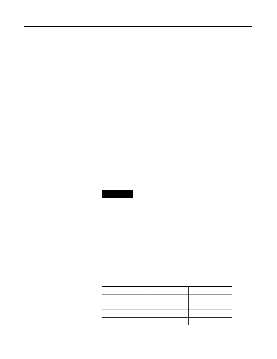
CState: Counter State Bits
These two bits show the operational state of the counter.
Table 2.3 Counter State Bit Settings
TIP
Counter overflow or underflow bits are reset when a
pulse in the opposite direction is received.
Bits 09 or 01
Bits 08 or 00
Operating State
0
0
Stopped
0
1
Running
1
0
Hold
1
1
Reserved