Single-ended encoder wiring (open collector) -9, 9 and 3-10, Single-ended encoder wiring (open collector) – Rockwell Automation 1746-HSCE2 Multi-Channel High Speed Counter Module User Manual
Page 49: Single-ended encoder output waveforms
Publication 1746-UM002B-EN-P - August 2004
Installation and Wiring 3-9
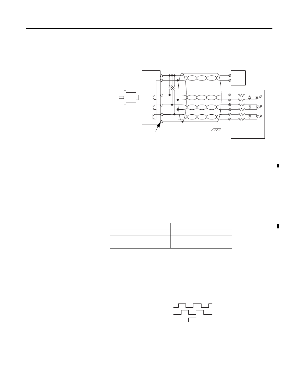
Single-Ended Encoder Wiring (Open Collector)
Figure 3.7 Single-Ended Encoder Wiring
(1) Refer to your encoder manual for proper cable type. The type of cable used should be twisted-pair, individually
shielded cable with a maximum length of 300m (1000 ft.).
(2) Calculate the value of the pull-up resistor (R), as shown below:
For 5V dc jumper position:
For 24V dc jumper position:
where:R = pull-up resistor value
Vcc = power supply voltage
Vmin = 4.2 V dc
Imin = 6.3 mA
Single-Ended Encoder Output Waveforms
The figure below shows the single-ended encoder output waveforms.
When the waveform is low, the encoder output transistor is on. When
the waveform is high, the encoder output transistor is off.
Figure 3.8 Single-Ended Encoder Output Waveforms
Power Supply Voltage (Vcc)
Pull-up Resistor Value (R)
5V dc
127
Ω
12V dc
238
Ω
24V dc
2140
Ω
A
B
Z
A1(+)
A1(–)
B1(+)
B1(–)
Z1(+)
Z1(–)
GND
VS
+VDC
COM
R
(2)
Cable
(1)
Power
Supply
Allen-Bradley
845H Series
single-ended
encoder
shield/housing
Connect only if housing is electronically
isolated from the motor and ground.
Shield
Module Inputs
Earth
R
Vcc
Vmin
–
(
)
Imin
--------------------------------------
=
R
Vcc
Vmin
–
(
)
Imin
--------------------------------------
1K
Ω
–
=
A
B
Z