Rockwell Automation 1746-HSCE2 Multi-Channel High Speed Counter Module User Manual
Page 111
Publication 1746-UM002B-EN-P - August 2004
Application Examples 6-19
4. Data word N10:11 was changed from 000C (hex) to 001C (hex)
to change the Counter 1 gate/preset mode from No Presets (000)
to Soft Presets Only (001).
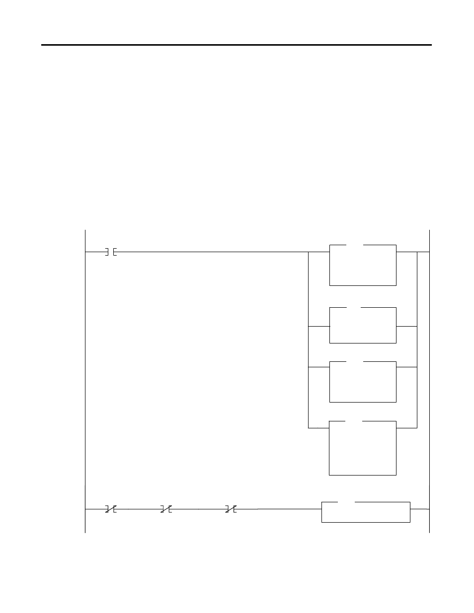
Ladder File 8 - HSCE2
0000
S:1
15
MOV
Move
Source
0
0 <
Dest
B3:0
0000000011000001<
MOV
MOV
Move
Source
0
0 <
Dest
N11:0
170 <
MOV
Fill File
Source
0
Dest
Length
8
#O:1.0
FLL
MUL
Multiply
Source A
10
10 <
Source B
N11:2
17 <
Dest
N11:1
170
<
MUL
0001
S:1
15
B3:0
0
B3:0
1
JSR
Jump To Subroutine
SBR File Number
U:9
JSR
FIRST_PASS
FIRST_PASS
HSCE2_INIT_DONE
HSCE2_ERROR
DATA_BLOCK_OFFSET
MAX_BLOCK_ADDR
#HSCE2_CFG_BLK
Prior to use, the programmer sets N11:2 to the total number of data blocks which will be entered into file N10 (not including the Counter Control
Block) and initializes the data blocks in file N10. Ten integer data blocks are used (instead of eight) to simplify the display in data windows.
The first pass of the program initializes the following values:
1. The HSCE2 initialization done bit (B3/0) is unlatched.
2. The HSCE2 error bit (B3/1) is cleared.
3. The Counter Configuration Block is cleared. Note: The init HSCE2 routine (ladder file 9) is bypassed during the first pass to ensure the
Configuration Data Block is reset prior to transfer of the first configuration data block.
While the HSCE2 is not initialized, and the HSCE2 has not errored, call the HSCE2 initialization routine.