Ladder file 9 - hsce2 initialization routine -17, Ladder file 9 - hsce2 initialization routine, See the ladder logic from example 2 on page 6-9 – Rockwell Automation 1746-HSCE2 Multi-Channel High Speed Counter Module User Manual
Page 109
Publication 1746-UM002B-EN-P - August 2004
Application Examples 6-17
Ladder File 8 Continued
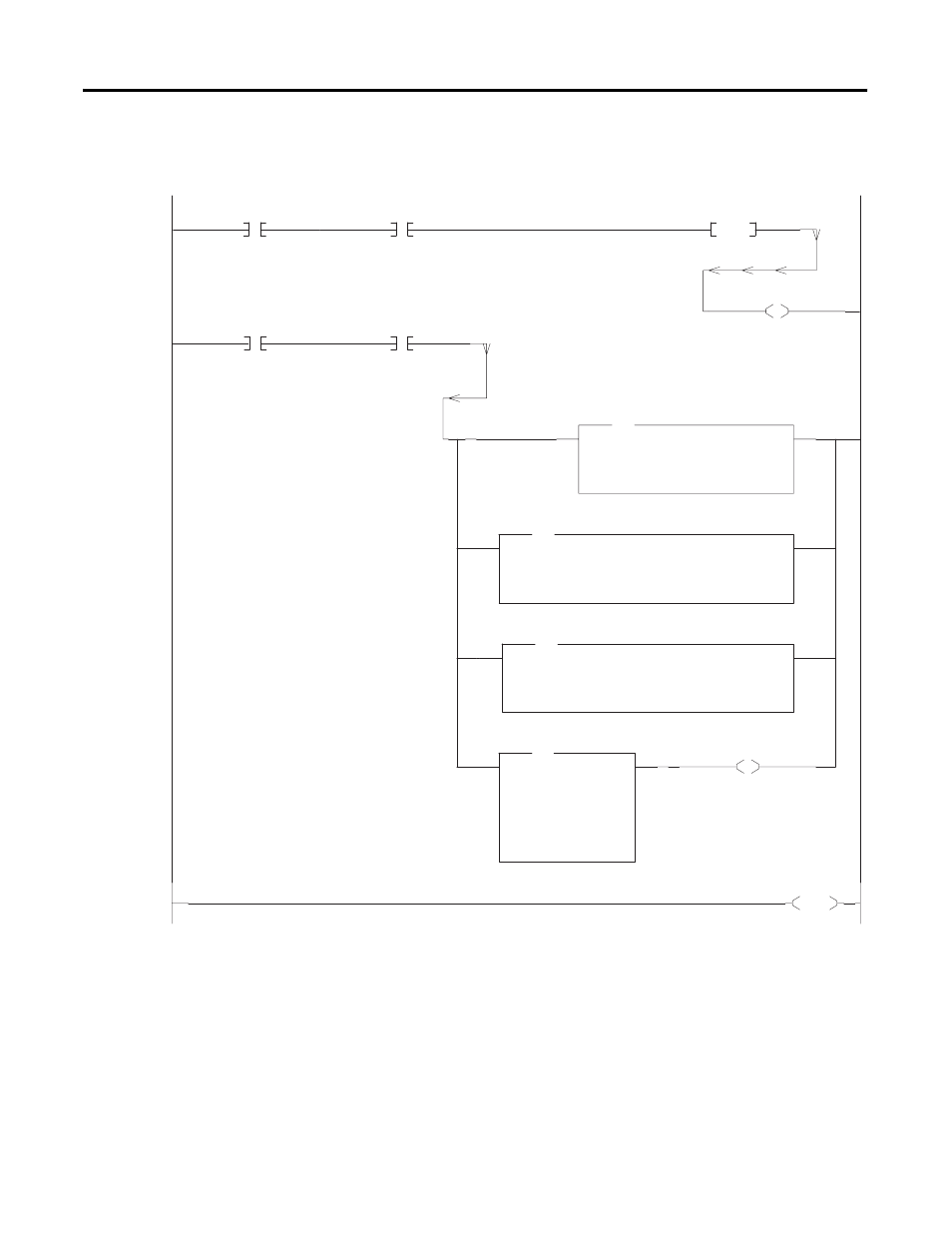
Ladder File 9 - HSCE2 Initialization Routine
See the ladder logic from Example 2 on page 6-9.
0003
B3:0
6
SOFT_PRESET_OSR
O:1
17
1746-HSCE2
HSCE2_CFG_BLK/17
CPT
Compute
Dest
F8:0
130.0<
Expression ( 1000.0 * I:1.2 ) + I:1.3
CTR1_COUNTS
CPT
Compute
Dest
F8:1
140.0<
Expression ( ( N10:25 * 1000.0 ) + N10:26 ) + 10.0
PRESET_UPPER_LIMIT
CPT
Compute
Dest
F8:2
120.0<
Expression ( ( N10:25 * 1000.0 ) + N10:26 ) - 10.0
CPT
PRESET_LOWER_LIMIT
LIM
Limit Test
Low Lim
F8:2
120.0<
Test
F8:0
130.0<
High Lim
F8:1
140.0<
LIM
CTR1_COUNTS
U
O:1
17
1746-HSCE2
HSCE2_CFG_BLK/17
0004
END
0002
B3:0
0
HSCE2_INIT_DONE
B3:0
6
SOFT_PRESET_TRGR
OSR
B3:0
7
SOFT_PRESET_OSR
L
O:1
17
1746-HSCE2
HSCE2_CFG_BLK/17
This rung implements a soft preset of counter 1 when the soft preset trigger bit sees a positive change (0 to 1). The rung assumes that the
Counter Control Block (last configuration block) is still in the output image to the 1746-HSCE2, and that Counter 1 permits soft presets.
After the soft preset is complete, unlatch the soft preset bit (O:1.1/1). To determine if the soft
preset is complete, compute the current counter 1 count value (F8:0), compute the valid preset
range (this example uses ±10 + PRESET VALUE from the Min/Max Count block), and compare.