Encoder wiring, Encoder wiring -8, Differential encoder wiring -8 – Rockwell Automation 1746-HSCE2 Multi-Channel High Speed Counter Module User Manual
Page 48: Differential encoder wiring, Differential encoder output waveforms
Publication 1746-UM002B-EN-P - August 2004
3-8 Installation and Wiring
Encoder Wiring
Differential encoders provide the best immunity to electrical noise. We
recommend, whenever possible, to use differential encoders.
The wiring diagrams on the following pages are provided to support
the Allen-Bradley encoders you may already own.
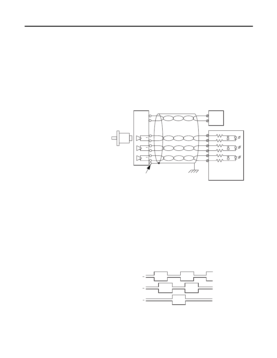
Differential Encoder Wiring
Figure 3.5 Differential Encoder Wiring
(1) Refer to your encoder manual for proper cable type. The type of cable used should be twisted pair, individually
shielded cable with a maximum length of 300m (1000 ft.).
Differential Encoder Output Waveforms
The Figure 3.6 shows the different encoder output waveforms. If your
encoder matches these waveforms, the encoder signals can be directly
connected to the associated screw terminals on the module. For
example, the A lead from the encoder is connected to the module’s
A+ screw. If your encoder does not match these waveforms, some
wiring modifications may be necessary. See Appendix B for a
description of these modifications.
Figure 3.6 Differential Encoder Output Waveforms
A
A
B
B
Z
Z
A1(+)
A1(–)
B1(+)
B1(–)
Z1(+)
Z1(–)
GND
VS
+VDC
COM
Cable
(1)
Power
Supply
Allen-Bradley
845H Series
differential
encoder
shield/housing
Connect only if housing is electronically
isolated from the motor and ground.
Shield
Module Inputs
Earth
A
A
B
B
Z
Z