Pgm n, Pgm n : program counter number bits, Ctype: counter type bit – Rockwell Automation 1746-HSCE2 Multi-Channel High Speed Counter Module User Manual
Page 62: Input config: input configuration bits
Publication 1746-UM002B-EN-P - August 2004
4-12 Configuration and Programming
PGMn: Program Counter Number Bits
(Word 0, Bits 08 to 11)
These four bits select the counters to which the programming block is
applied. If the bit is reset, the associated counter is not programmed
and the counter can be running when this block is sent. In addition,
the associated programming words must be zero or a programming
error occurs. A counter must be stopped when programmed with this
block.
CType: Counter Type Bit
(Words 1 and 3, Bit 00; Word 5, Bits 00 and 08)
For each counter, this bit defines whether the counter is a ring or
linear counter.
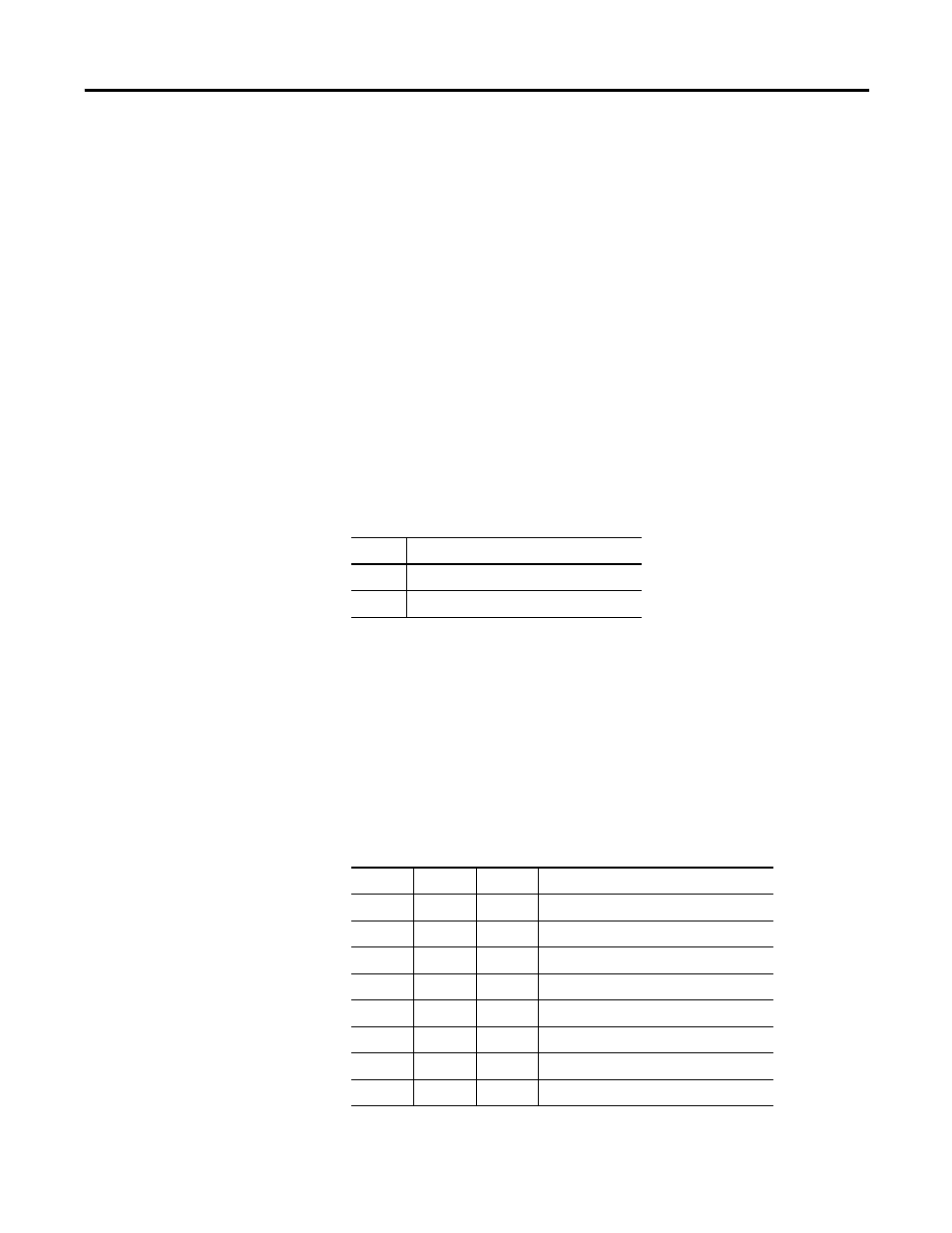
Input Config: Input Configuration Bits
(Words 1 and 3, Bits 01 to 03)
These bits define the input configuration for Counters 1 and 2.
Counters 3 and 4 are always Pulse/Internal Direction counters and do
not require programming bits. The table below shows the input
configuration programming bit values.
Table 4.3 Counter Type Programming Bit Settings
Bit
Counter Type
0
Ring Counter
1
Linear Counter
Table 4.4 Input Configuration Programming Bit Settings
Bit 03
Bit 02
Bit 01
Input Configuration
0
0
0
RESERVED
0
0
1
Up/Down Pulses
0
1
0
Pulse/External Direction
0
1
1
Pulse/Internal Direction
1
0
0
Quadrature X1
1
0
1
Quadrature X2
1
1
0
Quadrature X4
1
1
1
RESERVED