Counter control block, Counter control block -23 – Rockwell Automation 1746-HSCE2 Multi-Channel High Speed Counter Module User Manual
Page 73
Publication 1746-UM002B-EN-P - August 2004
Configuration and Programming 4-23
Output State on page 4-27 for a description of how the bytes are
combined.
If the start value is less than the stop value, the output state is applied
when the count or rate is within the range specified by the two values.
(For example, see ranges 1 through 3 on page 2-13.) If the start value
is greater than the stop value, the output state is applied when the
count or rate is outside the range. (For example, see range 4 on
page 2-13.) At least one of these bits must be set when programming a
range or a programming error is generated.
Counter Control Block
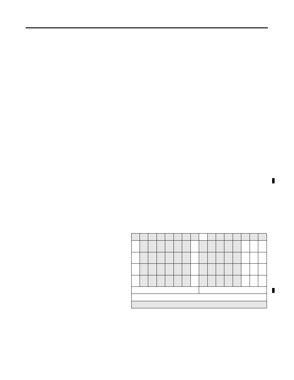
Figure 4.9 shows the format of the Counter Control programming
block. This block allows you to change the state of the following
counter controls for all four counters in one cycle:
• Enable/Disable Counter
• Soft Preset (if enabled)
• Internal Direction (if enabled)
• Output ON Mask
• Output Enable Mask
• Count or Rate Value (Class 1 only)
• Enable/Disable Range
All counters can be running when this block is sent to the module.
Figure 4.9 Counter Control Block Format
15 14 13 12 11 10 09 08 07 06 05 04 03 02 01 00
Word 0
0
0
0
0
0
0
0
0
1
0
0
0
0
0
0
0
Word 1
P1
0
0
0
0
0
0
C/R
1
0
0
0
0
0
ID1
SP1
EN1
Word 2
P2
0
0
0
0
0
0
C/R
2
0
0
0
0
0
ID2
SP2
EN2
Word 3
P3
0
0
0
0
0
0
C/R
3
0
0
0
0
0
ID3
SP3
EN3
Word 4
P4
0
0
0
0
0
0
C/R
4
0
0
0
0
0
ID4
SP4
EN4
Word 5
Output Enable Mask
Output ON (OR) Mask
Word 6
Enable Ranges
Word 7
RESERVED: Must Equal Zero