Power-up diagnostics, Channel diagnostics, Led indicators – Rockwell Automation 1746-NR8 SLC 500 RTD/Resistance Input Module User Manual User Manual
Page 86
Publication 1746-UM003A-EN-P
6-2 Module Diagnostics and Troubleshooting
Power-Up Diagnostics
At module power-up, a series of internal diagnostic self-tests is performed. The
module status LED remains off during power-up. The channel LEDs are
turned on until the self test has finished. If any diagnostic test fails, the module
enters the module error state. If all tests pass, the module status LED is turned
on and the channel status LED is turned on for the respective enabled channel.
The module continuously scans all enabled channels and communicates with
the SLC processor. During power- up, the RTD module does not
communicate with the processor.
Channel Diagnostics
When a channel is enabled (bit 11 = 1), a diagnostic check is performed to see
that the channel has been properly configured. In addition, the channel is
tested for out-of-range, open-circuit, and short-circuit faults on every scan.
A failure of any channel diagnostic test causes the faulted channel status LED
to blink. All channel faults are indicated in bits 13 through 15 of the channel’s
status word. Channel faults are self-clearing (bits 13 and 14 of status word). Bit
15 is not cleared until the correct change is made to the channel configuration.
The channel LED stops blinking and resumes steady illumination when the
fault conditions are corrected.
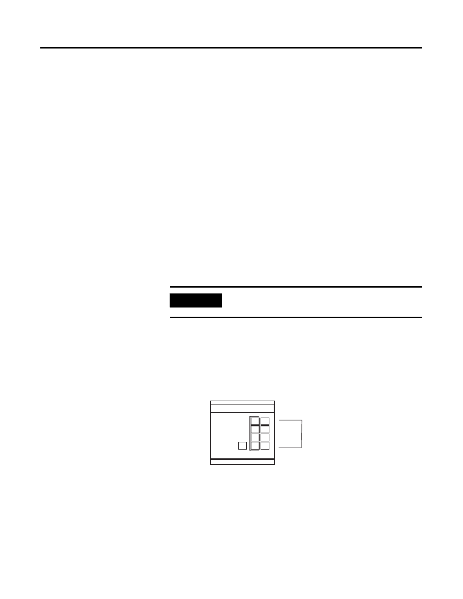
LED Indicators
The RTD module has nine LEDs. Eight of these are channel status LEDs
numbered to correspond to each of the RTD/resistance input channels and
one is a module status LED.
Figure 6.1 LED Display
IMPORTANT
If you clear (0) a channel enable bit (11), all channel status
information (including error information) is reset (0).
RTD / resistance
INPUT
MODULE
CHANNEL
ST ATUS
0 4
1 5
2 6
3 7
Channel LEDs