Rockwell Automation 1746-NR8 SLC 500 RTD/Resistance Input Module User Manual User Manual
Page 58
Publication 1746-UM003A-EN-P
4-10 Channel Configuration, Data, and Status
Configuration Words For User-set Scaling (Words 8 to 23)
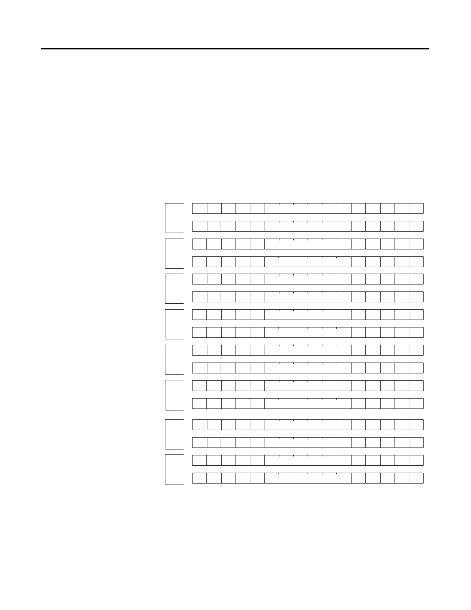
The following illustration shows the address of the user-set limit scale words
used to define the lower value and the upper value of the user-set scale words.
You can use the words for a channel when proportional counts mode is selected
for that channel
Any time proportional counts is selected and the upper limit is not zero, but is
equal to the lower limit, a configuration error occurs. For example, if both
scaling limits are 0, or if the lower range value is greater than or equal to the
upper range value, a configuration error occurs.
Figure 4.5 Limit Scale Words
Defines lower scale limit for Ch 0
Defines lower scale limit for Ch 1
Defines lower scale limit for Ch 2
Defines lower scale limit for Ch 3
Defines lower scale limit for Ch 4
Defines lower scale limit for Ch 5
Defines lower scale limit for Ch 6
Defines lower scale limit for Ch 7
Defines upper scale limit for Ch 0
Defines upper scale limit for Ch 7
Defines upper scale limit for Ch 6
Defines upper scale limit for Ch 1
Defines upper scale limit for Ch 2
Defines upper scale limit for Ch 3
Defines upper scale limit for Ch 4
Defines upper scale limit for Ch 5
Channel 0
Channel 7
Channel 6
Channel 1
Channel 2
Channel 3
Channel 4
Channel 5
O:e.8
O:e.9
O:e.10
O:e.11
O:e.12
O:e.13
O:e.14
O:e.15
O:e.16
O:e.17
O:e.18
O:e.19
O:e.20
O:e.21
O:e.22
O:e.23