Rockwell Automation 1746-NR8 SLC 500 RTD/Resistance Input Module User Manual User Manual
Page 30
Publication 1746-UM003A-EN-P
2-10 Installation and Wiring
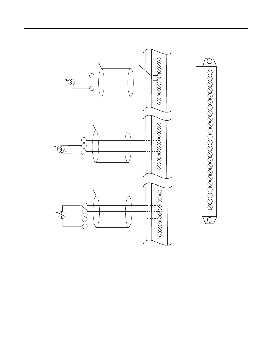
Figure 2.2 RTD Connections to Terminal Block
When using a 3-wire configuration, the module compensates for resistance
error due to lead wire length. For example, in a 3-wire configuration, the
module reads the resistance due to the length of one of the wires and assumes
that the resistance of the other wire is equal. If the resistances of the individual
lead wires are much different, an error may exist. The closer the resistance
values are to each other, the greater the amount of error that is eliminated.
2-Wire Interconnection
4-Wire Interconnection
3-Wire Interconnection
Cable Shield (Frame
Ground)
Cable Shield (Frame
Ground)
RTD
RTD
RTD
Return
Return
Return
Belden #9501 Shielded Cable
Sense
Sense
Belden #9533 Shielded Cable or
Belden #83503 Shielded Cable
Belden #9533 Shielded Cable or
Belden #83503 Shielded Cable
Leave One Sensor Wire Open
RTD 0
Sense 0
Return 0
RTD 1
Sense 1
Return 1
RTD 2
Sense 2
Return2
RTD 0
Sense 0
Return 0
RTD 1
Sense 1
Return 1
RTD 2
Sense 2
Return2
RTD 0
Sense 0
Return 0
RTD 1
Sense 1
Return 1
RTD 2
Sense 2
Return2
RTD 0
Sense 0
Return 0
RTD 1
Sense 1
Return 1
RTD 2
Sense 2
Return2
RTD 3
Sense 3
Return 3
RTD 4
Sense 4
Return 4
RTD 5
Sense 5
Return 5
RTD 6
Sense 6
Return 6
RTD 7
Sense 7
Return 7
Add
jumper
Cable Shield (Frame
Ground)