Rockwell Automation 1746-NR8 SLC 500 RTD/Resistance Input Module User Manual User Manual
Page 53
Publication 1746-UM003A-EN-P
Channel Configuration, Data, and Status 4-5
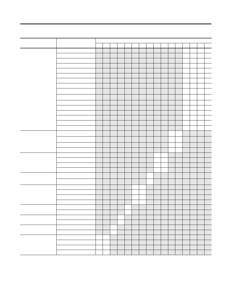
Table 4.1 Channel Configuration Word (O:e.0 through O:e.7) - Bit Definitions
Define
To Select
Make these bit settings in the Channel Configuration Word
15
14
13
12
11
10
9
8
7
6
5
4
3
2
1
0
Input type selection
100 Pt (385)
0
0
0
0
200 Pt (385)
0
0
0
1
500 Pt (385)
0
0
1
0
1000 Pt (385)
0
0
1
1
100 Pt (3916)
0
1
0
0
200 Pt (3916)
0
1
0
1
500 Pt (3916)
0
1
1
0
1000 Pt (3916)
0
1
1
1
10 Cu (426)
(1)
1
0
0
0
120 Ni (618)
(2)
1
0
0
1
120 Ni (672)
1
0
1
0
604 NiFe (518)
1
0
1
1
150
Ω
Resistance Input
1
1
0
0
500
Ω
Resistance Input
1
1
0
1
1000
Ω
Resistance Input
1
1
1
0
3000
Ω
Resistance Input
1
1
1
1
Data format selection
Engineering units x 1
(3)
0
0
Engineering units x 10
(4)
0
1
Scaled-for-PID
1
0
proportional counts
1
1
Broken input selection
Set to Zero
0
0
Set to Upscale
0
1
Set to Downscale
1
0
Invalid
1
1
Temperature units
selection
Degrees C
(5)
0
Degrees F
1
Filter frequency selection 28 Hz
0
0
50/60 Hz
0
1
800 Hz
1
0
6400 Hz
1
1
Channel enable
Channel Disabled
0
Channel Enabled
1
Excitation current
selection
1.0 mA
0
0.25 mA
1
Cal. Disable
Enable
0
Disable
1
Lead R. Enable
Disable
0
0
Periodic
0
1
Always
1
0
Invalid
1
1
(1) Actual value at 0 °C is 9.042
Ω
per SAMA standard RC21-4-1966.
(2) Actual value at 0 °C is 100
Ω
per DIN standard.
(3) Values are in 0.1 degree /step or 0.1
Ω
/step for all resistance input types, except 150
Ω
. For the 150
Ω
resistance input type, the values are in 0.01
Ω
/step.
(4) Values are in 1 degree /step or 1
Ω
/step for all resistance input types, except 150
Ω
. For the 150
Ω
resistance input type, the values are in 0.1
Ω
/step.