Rockwell Automation 1794-ID2 U.MNL INCREMENTAL ENCODER User Manual
Page 58
5–6
How Communication Takes Place and I/O Image Table Mapping with the DeviceNet Adapter
Publication 1794ĆUM015B-EN-P - May 2001
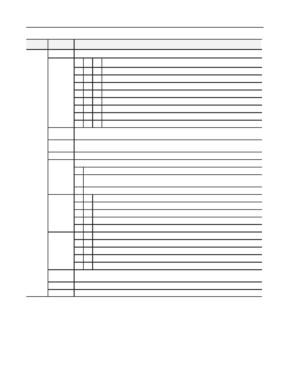
Definition
Bit
Word
Write
Word 1
0-15 (0-17) Control 0 - Control word for setting the function of counter 0.
Word 1
Bits 00-02
02 01 00 Mode Selection bits
0
0 0
Counting on positive (rising) edge of input signal A. (Up/dwn counting determined by B.)
0
0 1
Quadrature encoder X1
0
1 0
Quadrature encoder X2
0
1 1
Quadrature encoder X4
1
0 0
Counting up on the positive edge of input signal A, and down on positive edge of input signal B.
1
0 1
No count function.
1
1 0
No count function.
1
1 1
No count function.
Bit 03
Preset (Reset) bit - A positive edge on this bit moves the value in Preset X to Counter X, independent of Preset
Enable. NOTE: To use Preset as Reset, use a count value of 0000 in the Preset value word.
Bit 04
Enable Z Preset bit - When this bit is set (1), a positive edge on Z preloads Counter X = Preset X, independent of
Cal Enable. NOTE: If Z is configured to do Store and Preset (Reset), the Store will occur first.
Bit 05
Count Enable bit - When this is set (1), the incremental encoder is enabled.
Bits 06-08
(06 10)
Calibration Control bits - bits 06, 07 and 08
(06-10)
06 Enable bit - When this bit is set (1), the counter can be calibrated.
07 Direction bit - When this bit set (1), calibration is performed in a negative direction; when reset (0),
calibration is performed in a positive direction.
08 Reset bit - Calibration is acknowledged and a new calibration is enabled on a positive edge on this bit.
Bits 09-10
(11 12)
10 09 Gate Control bits
(11-12)
0
0 No gate function on input G
0
1 Counting only if G is high (active)
1
0 Counting only if G is low (inactive)
1
1 The counter can be calibrated when G is high (active).
Bits 11-12
(13 14)
12 11 Store Control bits
(13-14)
0
0 Save the counter value on the positive edge of Z (if Stored X = 0)
0
1 Save the counter value on the positive edge of G (if Stored X = 0)
1
0 Save the counter value on the negative edge of G (if Stored X = 0)
1
1 Save the counter value on the positive edge and negative edge of G (if Stored X = 0)
Bit 13 (15)
Rollover bit - When set (1), the counter counts up to the preset and then restarts at 0. If this bit is reset (0) (not
rollover), the rollover preset value = FFFF (hex = 65535 (decimal).
Bit 14 (16)
Store Reset bit - A positive edge on this bit resets Stored X in Signals.
Bit 15 (17)
Preset Reset bit - A positive edge on this bit resets Preset Detected in Signals.